Method and device for operating delivery pump
A technology of conveying pump and electric conveying, applied in the direction of muffler device, exhaust device, electric control of exhaust gas treatment device, etc., can solve the problem of difficult evaluation of current signal, and achieve the effect of minimizing noise
- Summary
- Abstract
- Description
- Claims
- Application Information
AI Technical Summary
Problems solved by technology
Method used
Image

Examples
Embodiment Construction
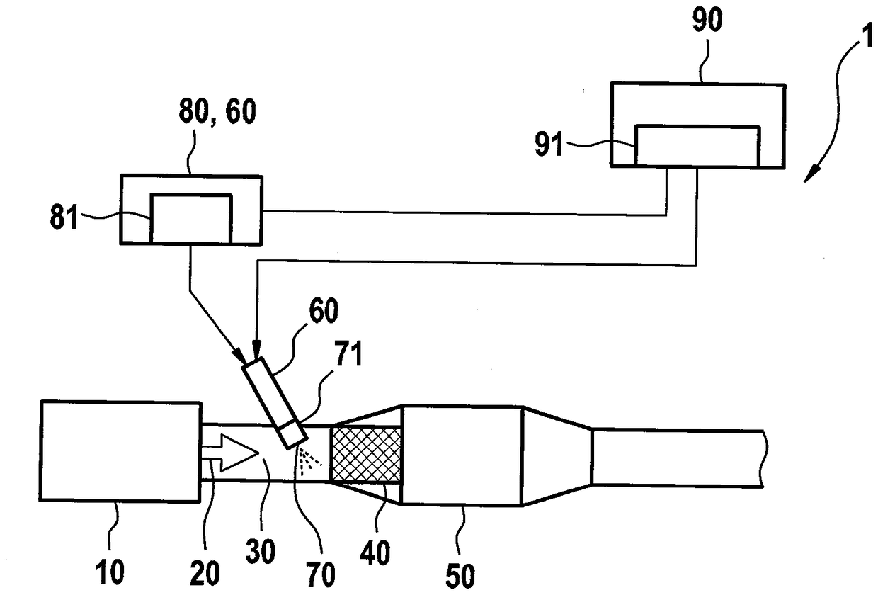
[0041] figure 1 By way of example, a technical environment is shown in which the method according to the invention can be used. Here, the illustration is limited to the components necessary for explaining the invention.
[0042] exist figure 1 An internal combustion engine 1 configured as a diesel motor is shown by way of example, which comprises a motor block 10 and an exhaust duct 30 in which an exhaust gas flow 20 is guided. The exhaust gas tract 30 has an exhaust gas purification device which, in the exemplary embodiment shown, firstly has an SCR catalytic converter 40 and a catalytically coated component arranged in the flow direction of the exhaust gas. Diesel particulate filter 50 (DPF). An injection unit 70 is arranged upstream of the SCR catalytic converter 40 on the exhaust tract 30 , with which injection unit urea-water solution can be injected. Together with the metering unit 80 , the injection unit 70 belongs to the metering system 60 , which can be controll...
PUM
 Abstract
Description
Claims
Application Information
 - Generate Ideas
- Intellectual Property
- Life Sciences
- Materials
- Tech Scout
- Unparalleled Data Quality
- Higher Quality Content
- 60% Fewer Hallucinations
Browse by: Latest US Patents, China's latest patents, Technical Efficacy Thesaurus, Application Domain, Technology Topic, Popular Technical Reports.
© 2025 PatSnap. All rights reserved.Legal|Privacy policy|Modern Slavery Act Transparency Statement|Sitemap|About US| Contact US: help@patsnap.com