Testing device and testing method for testing failure mechanism of contact surface between testing pile and grouting soil body

A technology of failure mechanism and test device, which is applied in the direction of measuring device, using stable shear force to test material strength, using stable tension/pressure to test material strength, etc., can solve the problem of poor pertinence, low precision, Problems such as the occurrence of shear failure surfaces can be achieved to improve the convenience of transportation, avoid load eccentricity, and facilitate connection and fixation

Pending Publication Date: 2018-12-11
GUANGZHOU ARCHITECTURE SCI RES INSTNEW TECH DEV CENT +1
View PDF0 Cites 5 Cited by
  • Summary
  • Abstract
  • Description
  • Claims
  • Application Information

AI Technical Summary

Problems solved by technology

[0003] At present, there is still a lack of in-depth and systematic research on the shearing, dislocation, and disengagement of the pile and its surrounding grouted soil, such as discontinuous deformation and failure problems.
The main reason is that the contact interface between the pile and the soil is assumed to be the failure surface during the operation of the existing test equipment, and the deformation of the two materials is coordinated. shear strength, so that the shear failure surface occurs inside the soil
The design concept of the current model pile test equipment makes it less pertinent to this test, the accuracy is not high, the test results are relatively random, and the operation is cumbersome. It is not suitable for a large number of model pile tests, so there is a lack of sufficient test data. comparative analysis

Method used


Image

  • Testing device and testing method for testing failure mechanism of contact surface between testing pile and grouting soil body
  • Testing device and testing method for testing failure mechanism of contact surface between testing pile and grouting soil body
  • Testing device and testing method for testing failure mechanism of contact surface between testing pile and grouting soil body

Examples


Embodiment Construction

[0038] The preferred embodiments of the present invention will be described below in conjunction with the accompanying drawings. It should be understood that the preferred embodiments described here are only used to illustrate and explain the present invention, and are not intended to limit the present invention.

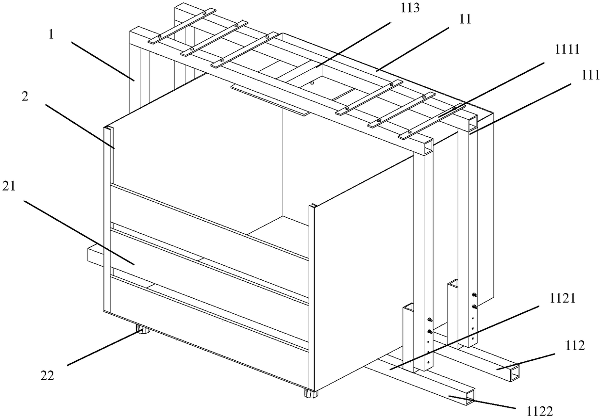
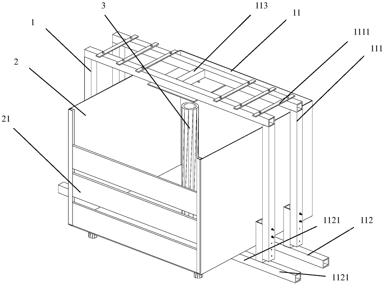
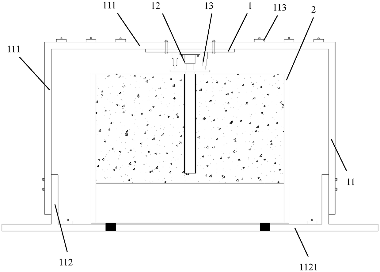
[0039] Such as Figure 1 ~ Figure 4 As shown, the test device for the failure mechanism of the test pile and the grouted soil contact surface of the present invention includes a loading device and a pipe pile model test box; The pile model test box provides a pressure loading mechanism; the pipe pile model test box is installed on the reaction frame.

[0040] The reaction frame includes an upper frame and a lower frame.

[0041] The upper frame includes at least two first rods arranged in parallel with an inverted "concave", preferably two; two adjacent first rods are connected by a connecting rod across the two. A connecting rod is arranged in the middle of the f...


PUM

PropertyMeasurementUnit
thicknessaaaaaaaaaa

Abstract

The invention provides a testing device for testing a failure mechanism of a contact surface between a testing pile and a grouting soil body. The testing device comprises a loading device and a tubular pile model test box; the loading device comprises a reaction force frame and a loading mechanism, and the loading mechanism arranged on the reaction force frame provides pressure to the tubular pilemodel test box; the tubular pile model test box is mounted on the reaction force frame, and the loading mechanism is arranged on the inner side of the top of the reaction force frame; the tubular pile model test box is detachably arranged in the reaction force frame; the loading mechanism is located above a tubular pile model mounting position of the tubular pile model test box; a displacement detecting device used for detecting vertical movement positions of the tubular pile model is arranged on the inner side of the top of the reaction force frame. The invention also provides a testing method for testing the failure mechanism of the contact surface between the testing pile and the grouting soil body by the testing device. Through the structure and the steps, the testing device is convenient to mount and demount and movable; a pile foundation model test system with accurate loading ensures smooth operation of tests, wherein strength and rigidity of the pile foundation model test system meet the test requirements.

Description

technical field [0001] The invention belongs to the technical field of civil engineering test devices, and in particular relates to a test device and a method for testing the failure mechanism of the interface between a pile and a grouted soil body. Background technique [0002] Pile foundation is a common form of foundation for high-rise buildings, especially in soft soil areas. The post-grouting technology on the pile side can reduce the thickness of the pile tip sediment, improve the performance of the pile tip and the soil around the pile, and has a significant effect on improving the bearing capacity of the pile and reducing the settlement of the pile. The interaction between the pile and the grouted soil is One of the main factors to play to strengths. The study of the mechanical characteristics of the interface between the pile and the grouted soil is the basis for understanding the mechanical mechanism of the grouted pipe pile, and the study of the mechanical charac...

Claims


Application Information

Patent Timeline
Patent Type & Authority Applications(China)
IPC IPC(8): G01N3/08G01N3/24
CPCG01N3/08G01N3/24G01N2203/0019G01N2203/0676G01N2203/0682
Inventor 戚玉亮唐孟雄吴声扬骆干
Owner GUANGZHOU ARCHITECTURE SCI RES INSTNEW TECH DEV CENT
Why Eureka
Try Eureka