Reaction chamber and plasma apparatus

A reaction chamber and chamber technology, applied in the field of plasma equipment, can solve problems affecting the uniformity of etching results, etc., and achieve the effects of ensuring long-term stability, improving air flow uniformity, and improving product yield

Pending Publication Date: 2018-12-11
BEIJING NAURA MICROELECTRONICS EQUIP CO LTD
View PDF0 Cites 8 Cited by
  • Summary
  • Abstract
  • Description
  • Claims
  • Application Information

AI Technical Summary

Problems solved by technology

The applicant found that the existing reaction chamber structure has the following defects: Due to the design requirement that friction cannot be generated between relative moving parts and the processing and installation errors of the inner lining 05 and the inner door 013, the gap between the inner door 013 and the inner lining 05 is inevitable. There will be a gap, generally 1-2mm, and the distribution of plasma inside the reaction chamber 09 will have a sudden change at the inner door, which will affect the uniformity of the etching result

Method used


Image

  • Reaction chamber and plasma apparatus
  • Reaction chamber and plasma apparatus
  • Reaction chamber and plasma apparatus

Examples


Embodiment Construction

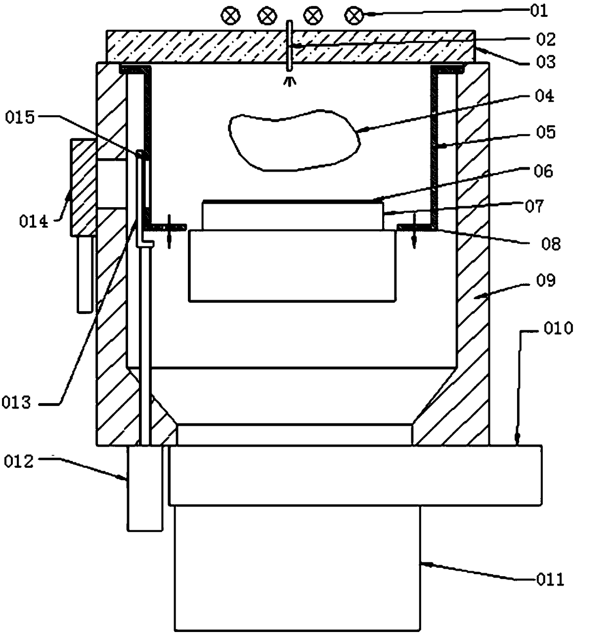
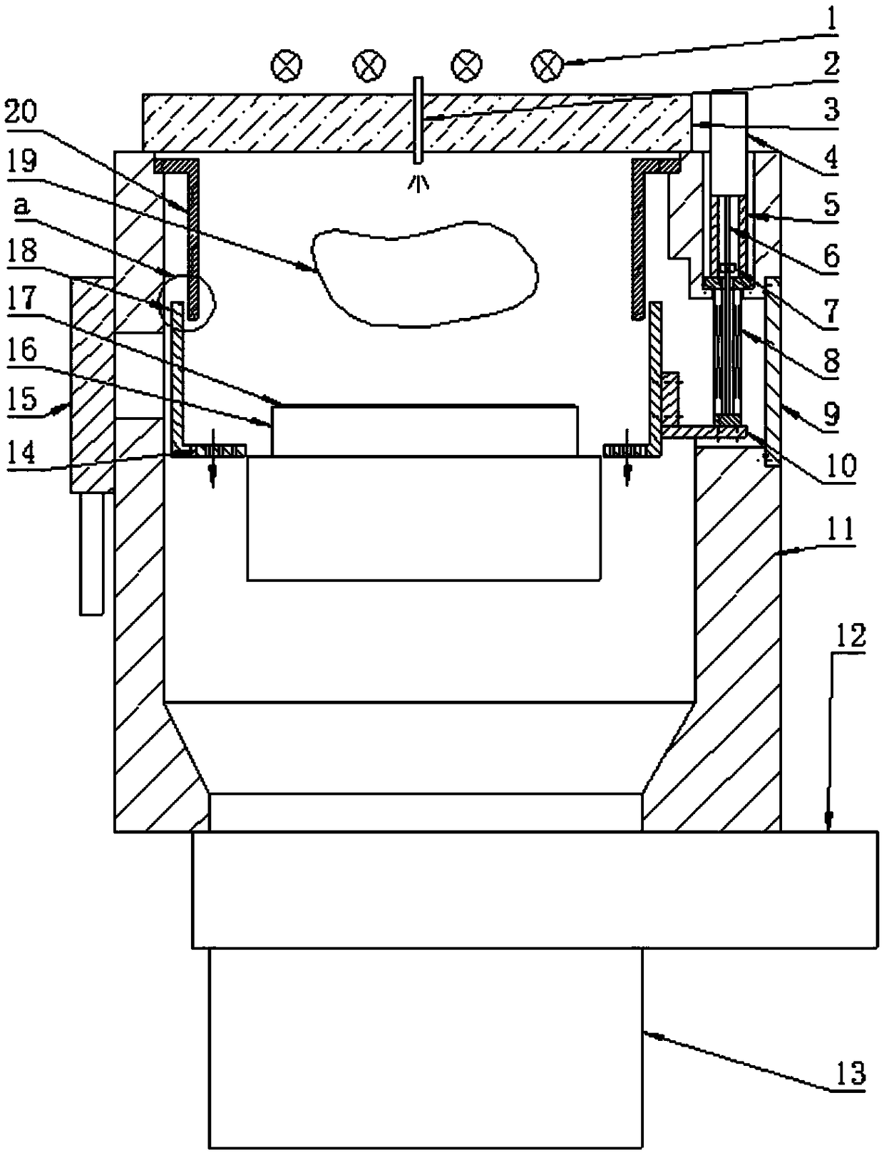
[0020] The present invention will be described more fully hereinafter with reference to the accompanying drawings, in which exemplary embodiments of the invention are illustrated. The following will clearly and completely describe the technical solutions in the embodiments of the present invention with reference to the accompanying drawings in the embodiments of the present invention. Obviously, the described embodiments are only some, not all, embodiments of the present invention. Based on the embodiments of the present invention, all other embodiments obtained by persons of ordinary skill in the art without making creative efforts belong to the protection scope of the present invention. The technical solution of the present invention will be described in various aspects in conjunction with the figures and embodiments below.

[0021] For the convenience of description below, the "left", "right", "upper" and "lower" referred to below are consistent with the left, right, upper ...


PUM


Abstract

The embodiment of the invention discloses a reaction chamber and a plasma apparatus. The reaction chamber comprises a chamber body, an inner liner, a support assembly and a lifting driving device. Theliner includes a first liner and a second liner; The second liner is coaxially sleeved or sleeved on the first liner and has a gap between the first liner and the second liner, and the lifting and lowering driving device is used for driving the second liner up or down; When the wafer is processed, the length of the overlapping portion of the first liner and the second liner is a predetermined length such that the wafer is located in a process region surrounded by the first liner and the second liner. According to the present invention, The plasma can be confined in a certain process area in the process treatment process, the inner wall of the chamber body can be protected from etching, the gas flow uniformity in the process is improved, the process is stable for a long time, the etching result from the center to the edge of the wafer is consistent, and the yield of the product is improved.

Description

technical field [0001] The invention relates to the technical field of semiconductor manufacturing, in particular to a reaction chamber and plasma equipment. Background technique [0002] Plasma equipment is widely used in today's semiconductor, solar cell, flat panel display and other manufacturing processes. In the current manufacturing process, various types of plasma equipment have been used, such as capacitively coupled plasma, inductively coupled plasma, and electron cyclotron resonance plasma. These types of discharges are currently widely used in physical vapor deposition, plasma etching, and plasma chemical vapor deposition. [0003] figure 1 It is an existing common reaction chamber structure used for semiconductor dry etching equipment. The process gas flows into the interior of the reaction chamber 09 through the inlet channel 02, and the high-frequency energy generated by the upper electrode RF antenna 01 passes through the dielectric window 03 to ionize the ...

Claims


Application Information

Patent Timeline
Patent Type & Authority Applications(China)
IPC IPC(8): H01J37/32
CPCH01J37/32449H01J37/32458H01J37/32504H01J2237/334
Inventor 王伟
Owner BEIJING NAURA MICROELECTRONICS EQUIP CO LTD
Why Eureka
Try Eureka