Adoubly-fed induction generatorcontrol method based on an energy storage device

A generator control and energy storage device technology, which is applied in the direction of asynchronous generator control, wind power generation, control generator, etc., can solve the problems of large fluctuations in the voltage of the DC bus, improve voltage stability, reduce capacity, and improve The effect of terminal voltage dynamic performance

Inactive Publication Date: 2018-12-11
NANJING UNIV OF SCI & TECH
View PDF4 Cites 8 Cited by
  • Summary
  • Abstract
  • Description
  • Claims
  • Application Information

AI Technical Summary

Problems solved by technology

[0005] The purpose of the present invention is to provide a doubly-fed induction generator control method with an energy storage device, which is used to...

Method used


Image

  • Adoubly-fed induction generatorcontrol method based on an energy storage device
  • Adoubly-fed induction generatorcontrol method based on an energy storage device
  • Adoubly-fed induction generatorcontrol method based on an energy storage device

Examples


Embodiment

[0055] The control method of this example comprises the following steps:

[0056] 1. Initialize each parameter, the wind turbine adopts the per unit value model, and the rated power P n = 1MVA; doubly-fed induction generator parameters: stator resistance r s =3.569e-3Ω, stator resistance r r =3.654e-3Ω, stator leakage inductance L ls =0.1304e-3H, rotor leakage inductance L lr =0.1198e-3H, stator and rotor mutual inductance L m =4.12e-3H, rated power P n =1MVA, rated speed w r = 2160r / min, rated frequency f = 60Hz, number of pole pairs p = 2; capacitance parameters: capacitance: C = 0.01F, capacitance voltage U dc =1200V; grid parameters: voltage U m =575V, frequency f=60Hz.

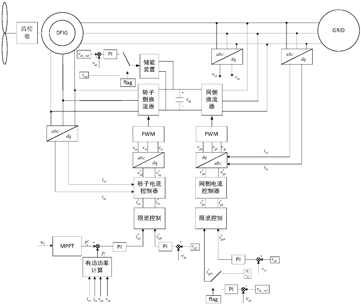
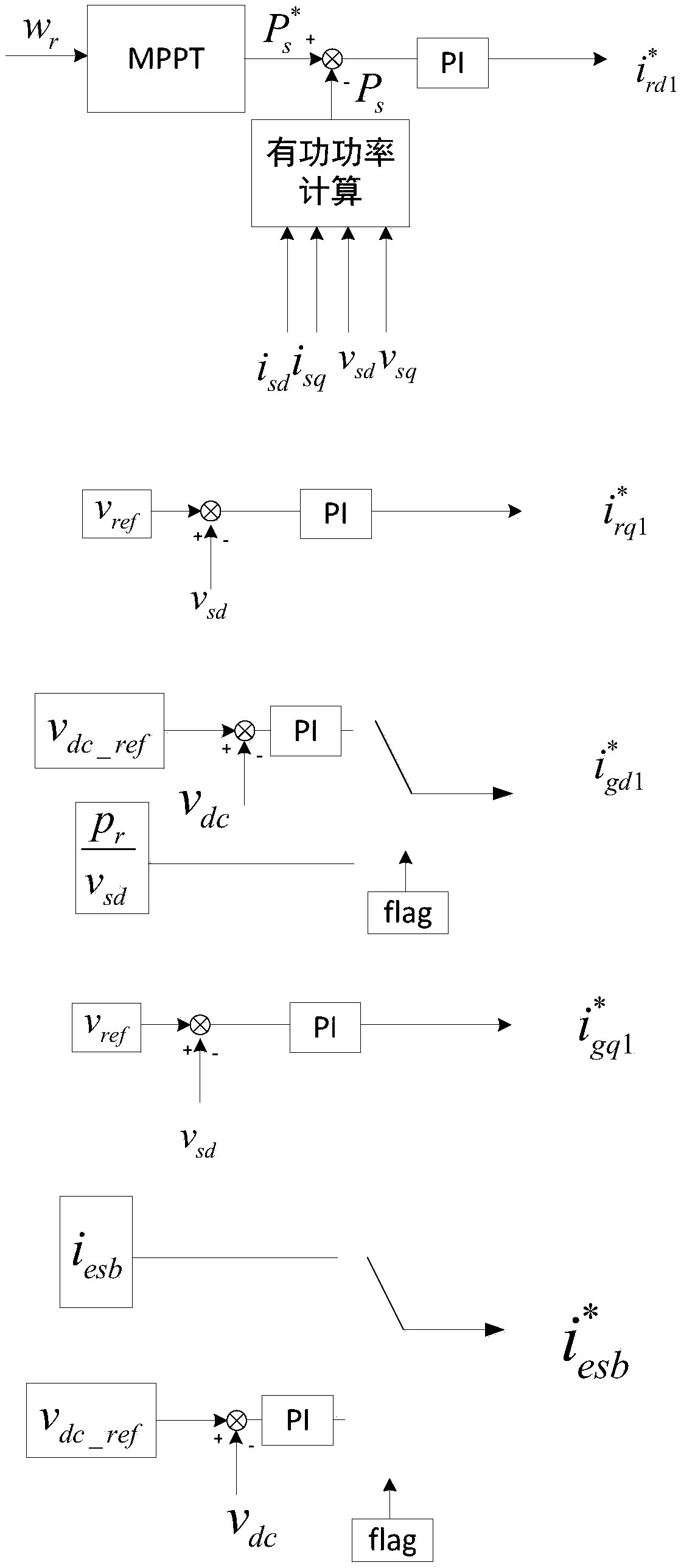
[0057] 2. The overall control strategy adopts stator voltage orientation, namely The d-axis control strategy of the rotor-side converter adopts the power outer loop and the current inner loop. Such as image 3 As shown, the power reference value of the outer ring is p s_ref * , which is gene...


PUM


Abstract

The invention provides a doubly-fed induction generator control method based onan energy storage device. The energy storage deivceis mainly used for maintaining the voltage stability of a fault transient DC bus of a power network. The specific method is that the energy storage device is connected with the DC bus, the rotor-side converter adopts constant voltage, and the grid-side converter cooperates with the control strategy of the energy storage device to keep the DC bus voltage constant. When a fault occurs at the connection point, the voltage drop of the connection point is detected, and then the energy storage device is put into use to stabilize the voltage of the DC bus bar during the fault. At the same time, as the DC bus voltage is no longer controlled by the grid-side converter, the grid-side current command is calculated according to the active power of the rotor side, which is used for the transmission of the active power from the rotor side to the power grid. At that same time, the residual capacity of the rotor convert can be used to output reactive pow to the power network and to support the voltage of the parallel connection point. The invention has the advantages ofimproving the voltage dynamic performance of the machine terminal, improving the voltage stability of the DC bus bar, reducing the capacity of the energy storage device and the like.

Description

technical field [0001] The invention belongs to the technical field of wind power generation, in particular to a control method for a doubly-fed induction generator with an energy storage device. Background technique [0002] The double-fed induction generator (DFIG) is driven by the wind turbine through the gearbox. The stator of the double-fed wind generator is directly connected to the grid and directly transmits power to the grid. The rotor realizes the frequency through the "back-to-back" dual PWM converter. Transformation, so that the rotor current frequency and rotor speed meet the stator frequency and grid frequency, and transmit or absorb power to the grid according to the difference in slip. [0003] The doubly-fed induction generator occupies an important position in the wind power industry due to its advantages such as large speed range adjustment, rotor transmission power only slip power, and small converter capacity. [0004] During the grid fault and recovery...

Claims


Application Information

Patent Timeline
IPC IPC(8): H02J3/38H02P9/10H02P101/15H02P103/10
CPCH02J3/386H02P9/105H02P2101/15H02P2103/10Y02E10/76
Inventor 王文辉孙晓敏江宁强张杰全亚明张凌雪胡继磊
Owner NANJING UNIV OF SCI & TECH
Why Eureka
Try Eureka