Prefabricated self-heat-preservation shearing wall

A technology of shear wall and self-insulation, which is applied in the field of construction engineering, can solve the problems of affecting the overall performance of wall panels, occupying building area, and poor insulation effect, etc., and achieves the advantages of simple structure, reduced occupation, enhanced integrity and mechanical performance Effect

Inactive Publication Date: 2018-12-14
NINGBO PRECA CONSTR TECH CO LTD
View PDF8 Cites 0 Cited by
  • Summary
  • Abstract
  • Description
  • Claims
  • Application Information

AI Technical Summary

Problems solved by technology

Most of the existing shear wall structure buildings are poured layer by layer on site, and then external insulation is applied. This method of construction is difficult, time-consuming and labor-intensive. With the rapid development of my country's construction industry and the improvement of awareness of green energy conservation and environmental protection , prefabricated buildings emerged as the times require, and shear walls are gradually adopting prefabricated shear walls
[0003] At present, there are generally two types of prefabricated thermal insulation shear walls. One is the laminated shear wall, which uses truss bars to connect the inner and outer blades, and the middle insulation layer is filled later. This kind of shear wall not only has poor insulation effect 1. The construction is complicated, and the location of the truss bars will form a cold bridge, which will affect the overall performance of the wall panel; the second is the sandwich thermal insulation shear wall, that is, the fiber connector or steel connector is used to connect the inner and outer blades and the middle insulation layer, but The outer blades are only connected by connectors, which are easy to fall off and have poor durability
Moreover, the thickness of these two kinds of shear walls is more than 300mm, even as high as 400mm, which greatly occupies the building area.

Method used


Image

  • Prefabricated self-heat-preservation shearing wall
  • Prefabricated self-heat-preservation shearing wall
  • Prefabricated self-heat-preservation shearing wall

Examples


Embodiment 1

[0039] The glass pumice concrete layer 2 includes the following components in parts by weight: 450 parts of ordinary Portland cement with a strength grade of 42.5, 50 parts of fly ash, 2.55 parts of polycarboxylate superplasticizer, 2 parts of polypropylene short fiber, 620 parts of medium sand with a fineness modulus of 3.0-2.3, 280 parts of closed-cell glass pumice with a continuous gradation of 5-30 mm, mix the above components according to the proportion, add to the mixer and stir for 1-2 minutes, then add 165 parts of water parts, and then stirred for 3-5min.

[0040] The preparation method of the above-mentioned glass pumice concrete layer 2, according to the following components by weight, 450 parts of cement, 50 parts of fly ash, 2.55 parts of water reducing agent, 2 parts of fiber, 620 parts of medium sand, and 280 parts of glass pumice , 165 parts of water, mixed and stirred, added to the mold, and the mold was removed after natural drying. The dry density of the gl...

Embodiment 2

[0042] The glass pumice concrete layer 2 includes the following components in parts by weight: 450 parts of ordinary Portland cement with a strength grade of 42.5, 50 parts of fly ash, 2.65 parts of polycarboxylate superplasticizer, 2 parts of polypropylene short fiber, 680 parts of medium sand with a fineness modulus of 3.0-2.3, 296 parts of closed-cell glass pumice with a continuous gradation of 5-30mm, mix the above components according to the proportion, add to the mixer and stir for 1-2min, then add 165 parts of water parts, and then stirred for 3-5min.

[0043] The preparation method of the above-mentioned glass pumice concrete layer 2, according to the following components by weight, 450 parts of cement, 50 parts of fly ash, 2.65 parts of water reducing agent, 2 parts of fiber, 680 parts of medium sand, and 296 parts of glass pumice , 165 parts of water, mixed and stirred, added to the mold, and the mold was removed after natural drying. The dry density of the glass pu...

Embodiment 3

[0045] The glass pumice concrete layer 2 includes the following components in parts by weight: 500 parts of ordinary Portland cement with a strength grade of 42.5, 50 parts of fly ash, 2.75 parts of polycarboxylate superplasticizer, 2 parts of polypropylene short fiber, 730 parts of medium sand with a fineness modulus of 3.0-2.3, 300 parts of closed-cell glass pumice with a continuous gradation of 5-30 mm, mix the above components according to the proportion, add them to the mixer and stir for 1-2 minutes, then add 165 parts of water parts, and then stirred for 3-5min.

[0046] The preparation method of the above-mentioned glass pumice concrete layer 2, according to the following components by weight, 500 parts of cement, 50 parts of fly ash, 2.75 parts of water reducing agent, 2 parts of fiber, 730 parts of medium sand, and 300 parts of glass pumice , 165 parts of water, mixed and stirred, added to the mold, and the mold was removed after natural drying. The dry density of the...


PUM

PropertyMeasurementUnit
thicknessaaaaaaaaaa
thicknessaaaaaaaaaa
densityaaaaaaaaaa

Abstract

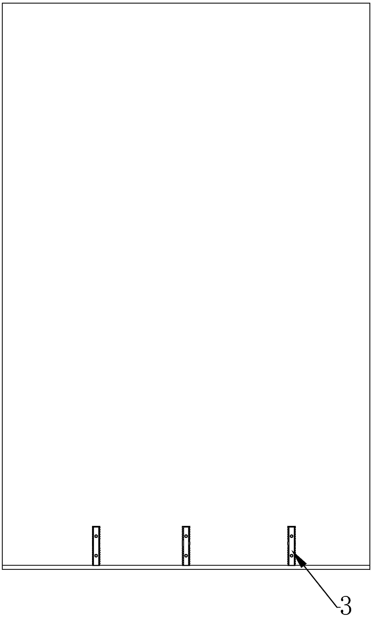
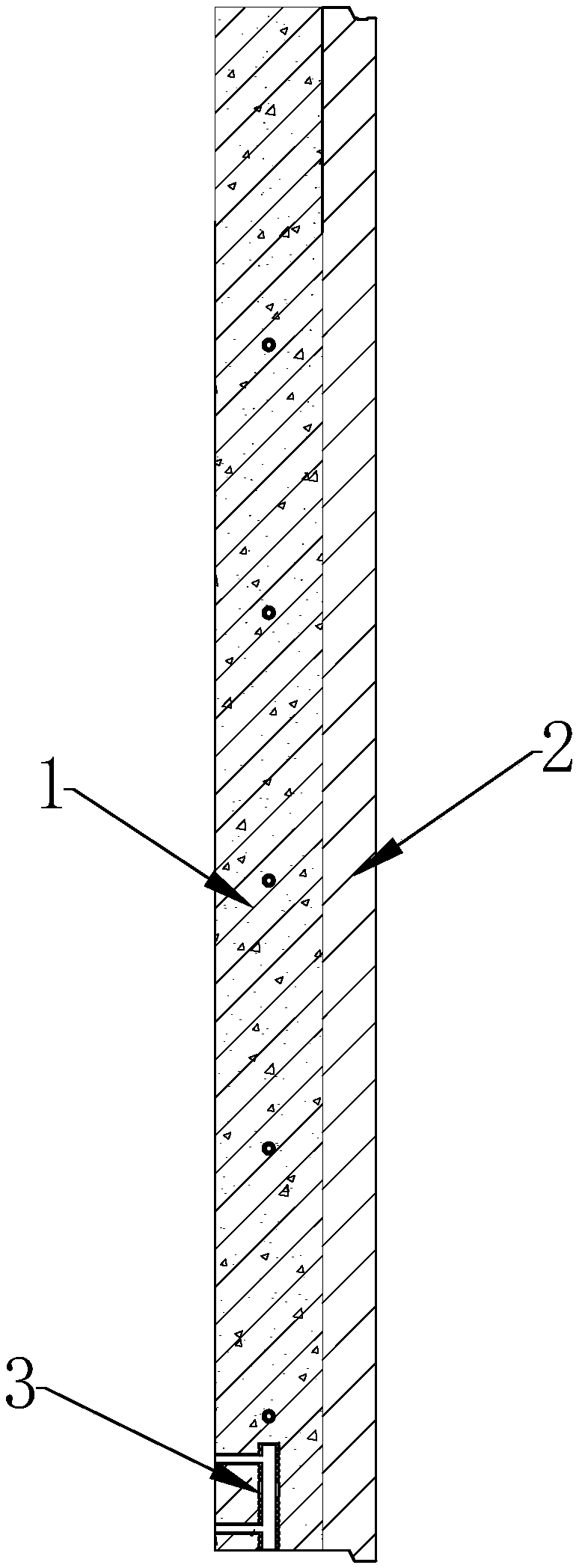
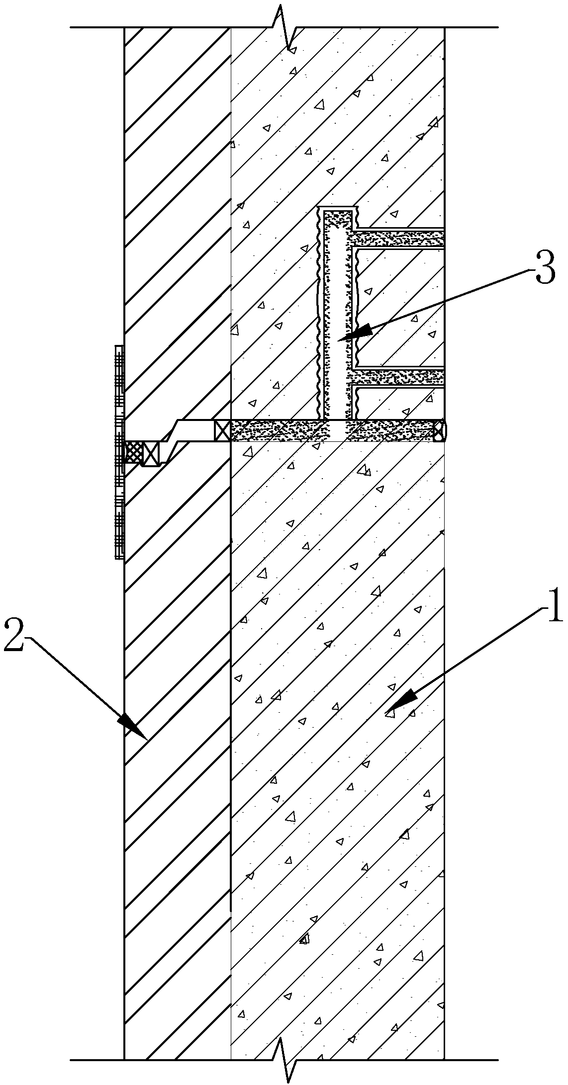
The invention discloses a prefabricated self-heat-preservation shearing wall which comprises a common concrete layer and a glass pumice concrete layer, wherein double-layer bidirectional reinforcing steel bars are arranged in the common concrete layer; single-layer bidirectional reinforcing steel bars are arranged in the glass pumice concrete layer; the double-layer bidirectional reinforcing steelbars and the single-layer bidirectional reinforcing steel bars are fixed through U-shaped ribs and tying bars to form a reinforcement cage; the glass pumice concrete layer comprises the following components in parts by weight: 400-650 parts of cement, 20-60 parts of coal ash, 120-200 parts of water, 1.5-3.5 parts of a water reduction agent, 0.8-3.2 parts of a fiber, 620-800 parts of medium sand of which the fineness modulus is 3.0-2.3, and 250-320 parts of continuously graded glass pumice of 5-30mm. The shearing wall is good in heat preservation effect, small in thickness, good in durabilityand free of cold bridge phenomenon.

Description

technical field [0001] The invention relates to the technical field of construction engineering, in particular to a prefabricated self-insulating shear wall. Background technique [0002] Shear walls have the advantage of being able to bear vertical loads and horizontal loads, and can be both load-bearing and enclosure. Therefore, in the field of construction, we usually use shear wall structures for buildings that require higher overall strength. Most of the existing shear wall structure buildings are poured layer by layer on site, and then external insulation is applied. This method of construction is difficult, time-consuming and labor-intensive. With the rapid development of my country's construction industry and the improvement of awareness of green energy conservation and environmental protection , Assembled buildings came into being, and the shear walls are gradually adopting prefabricated shear walls. [0003] At present, there are generally two types of prefabricate...

Claims


Application Information

Patent Timeline
Patent Type & Authority Applications(China)
IPC IPC(8): C04B28/04C04B28/02
CPCC04B28/02C04B28/04C04B2201/32C04B2201/50C04B18/08C04B2103/302C04B16/0633C04B14/06C04B14/24
Inventor 蒋义刘铁周林根陈静何喜
Owner NINGBO PRECA CONSTR TECH CO LTD
Why Eureka
Try Eureka