
Additive manufacturing method for laser-assisted laser cladding

A laser cladding and additive manufacturing technology, which is applied in the directions of additive manufacturing, additive processing, and process efficiency improvement. The effect of forming quality and improving the degree of densification

Inactive Publication Date: 2018-12-18
JIANGSU UNIV
View PDF4 Cites 5 Cited by
  • Summary
  • Abstract
  • Description
  • Claims
  • Application Information

AI Technical Summary

Problems solved by technology

[0004] However, the traditional heat treatment method can no longer solve the defects of laser cladding technology. For example, the substrate preheating method increases the heating process, which reduces the production efficiency and deteriorates the working conditions. It is especially obvious for the laser cladding process of large parts. The surface of the component is oxidized due to long-term heating, which weakens the performance of the cladding layer, resulting in a decrease in hardness, wear resistance and corrosion resistance

Method used


Image

  • Additive manufacturing method for laser-assisted laser cladding
  • Additive manufacturing method for laser-assisted laser cladding
  • Additive manufacturing method for laser-assisted laser cladding

Examples


Embodiment 1

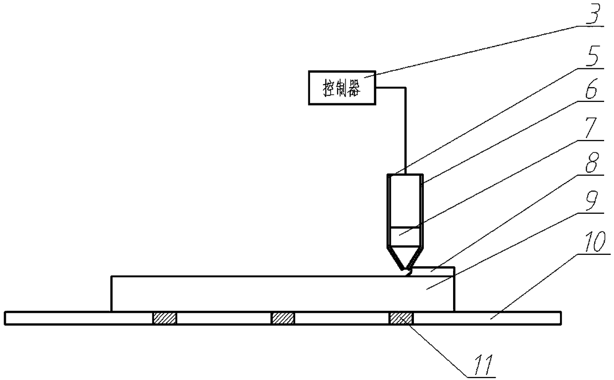
[0025] Such as figure 1 As shown, fix the TC4 substrate on the workbench with a fixture, use the laser cladding device, adopt the above laser cladding process parameters, along the Figure 4 The path shown in the plan is to carry out laser cladding on the surface of the substrate. After the first layer of cladding is completed, the above-mentioned laser cladding process parameters are still used, and the following steps are still followed: Figure 4 The planned path shown for the second layer of cladding.

Embodiment 2

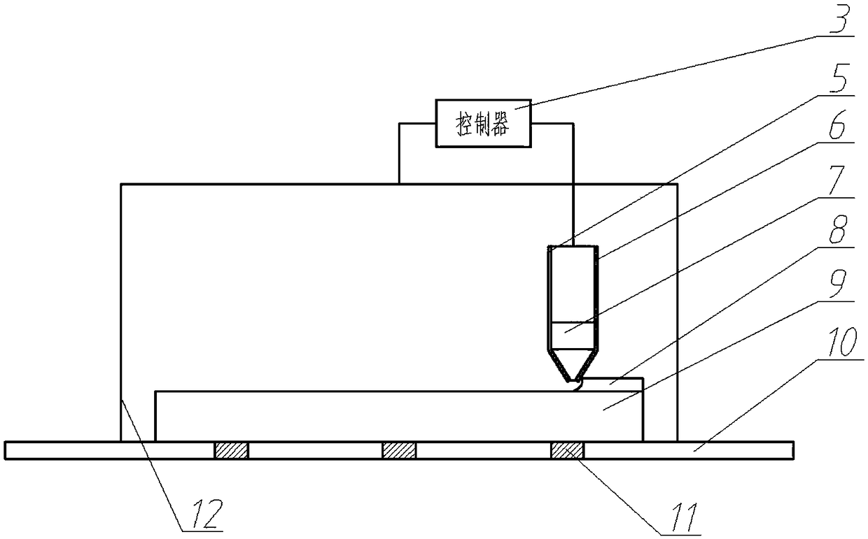
[0027] Such as figure 2 As shown, the TC4 substrate is fixed on the workbench with a fixture, the heating device is heated to 500.11°C, and kept at this temperature, and then the laser cladding device is used, and the above laser cladding process parameters are adopted, along the lines as Figure 4 The path shown in the plan is to carry out laser cladding on the surface of the substrate. After the first layer of cladding is completed, the above-mentioned laser cladding process parameters are still used, and the following steps are still followed: Figure 4 The planned path shown for the second layer of cladding.

Embodiment 3

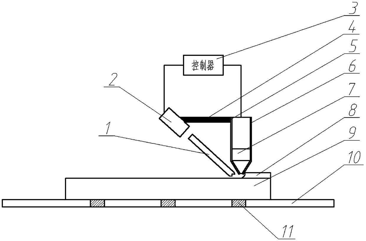
[0029] Technical scheme of the present invention, such as image 3 As shown, 1) fix the TC4 substrate on the workbench with a fixture; 2) first use a continuous laser beam to locally heat the initial position of the substrate surface to the dynamic recrystallization temperature of the substrate at 500.11 °C; 3) immediately use laser melting The cladding device adopts the above laser cladding process parameters to carry out laser cladding on the same position, and adopts the same operation steps, along the Figure 4 The pre-planned path shown is to complete the first layer of cladding; in order to ensure simultaneous laser heating and laser cladding at the same position, where the laser-heated light outlet is connected with the laser cladding head, the two parts are together during processing 4) Then use a continuous laser beam to locally heat the initial position of the cladding layer surface to the dynamic recrystallization temperature of the cladding layer 500.11 ° C; 5) Imm...


PUM


Abstract

The invention relates to an additive manufacturing technology for laser cladding, and specifically relates to an additive manufacturing method for laser-assisted laser cladding. The additive manufacturing method for laser-assisted laser cladding comprises the following steps: firstly carrying out local heating on the initial position of the surface of a substrate by virtue of a continuous laser beam to reach a dynamic recrystallization temperature of the substrate, then immediately carrying out laser cladding on the same position by virtue of a laser cladding device, and completing first-layercladding along a path planned in advance through the same operation steps; then carrying out laser heating on the initial position of the surface of a clad layer by virtue of the continuous laser beam to reach a dynamic recrystallization temperature of the clad layer; then immediately carrying out laser cladding on the same position by virtue of the laser cladding device, and completing second-layer cladding along a path planned in advance through the same operation steps; and repeating in this way to complete additive manufacturing for a metal workpiece.

Description

technical field [0001] The invention relates to the additive manufacturing technology of laser cladding, in particular to a laser-assisted laser cladding additive manufacturing method. Background technique [0002] Laser cladding technology is widely used in aerospace, chemical industry, mold, machinery, steel and other industries due to its controllable heat source and rapid solidification, high bonding strength and fine structure. However, there are still some problems in the laser cladding process. The main problems include defects such as pores, cracks, and coarse columnar grains in the cladding layer, as well as large residual stress due to rapid heating and quenching during the laser cladding process. At present, the solutions to these defects mainly include reducing these problems by adding some special alloy elements or rare earth oxides, or by optimizing the laser cladding process and preheating and postheating. , porosity and residual stress have no breakthrough. ...

Claims


Application Information

Patent Timeline
IPC IPC(8): B22F3/105C23C24/10B33Y10/00B33Y30/00
CPCC23C24/103B22F3/003B33Y10/00B33Y30/00B22F10/00B22F10/322B22F10/36B22F10/28B22F10/366Y02P10/25
Inventor 鲁金忠卢海飞罗开玉
Owner JIANGSU UNIV
Learn More