Welding structure of metal defect digging-patching welding groove of steel casting and reinforcing method of welding structure

A technology for metal defects and welding structures, which is applied in welding equipment, metal processing equipment, and edge parts of workpieces. problems, to achieve the effect of inhibiting harmful effects and improving thermal field distribution

Active Publication Date: 2018-12-18
哈尔滨中正焊接技术开发有限公司 +6
View PDF6 Cites 2 Cited by
  • Summary
  • Abstract
  • Description
  • Claims
  • Application Information

AI Technical Summary

Problems solved by technology

[0008] The present invention solves the problem of excessive welding volume in the repair welding area, difficulty in controlling welding deformation, poor overall crack resistance, poor welding structure stability and fatigue resistance in existi

Method used


Image

  • Welding structure of metal defect digging-patching welding groove of steel casting and reinforcing method of welding structure
  • Welding structure of metal defect digging-patching welding groove of steel casting and reinforcing method of welding structure
  • Welding structure of metal defect digging-patching welding groove of steel casting and reinforcing method of welding structure

Examples


Example Embodiment

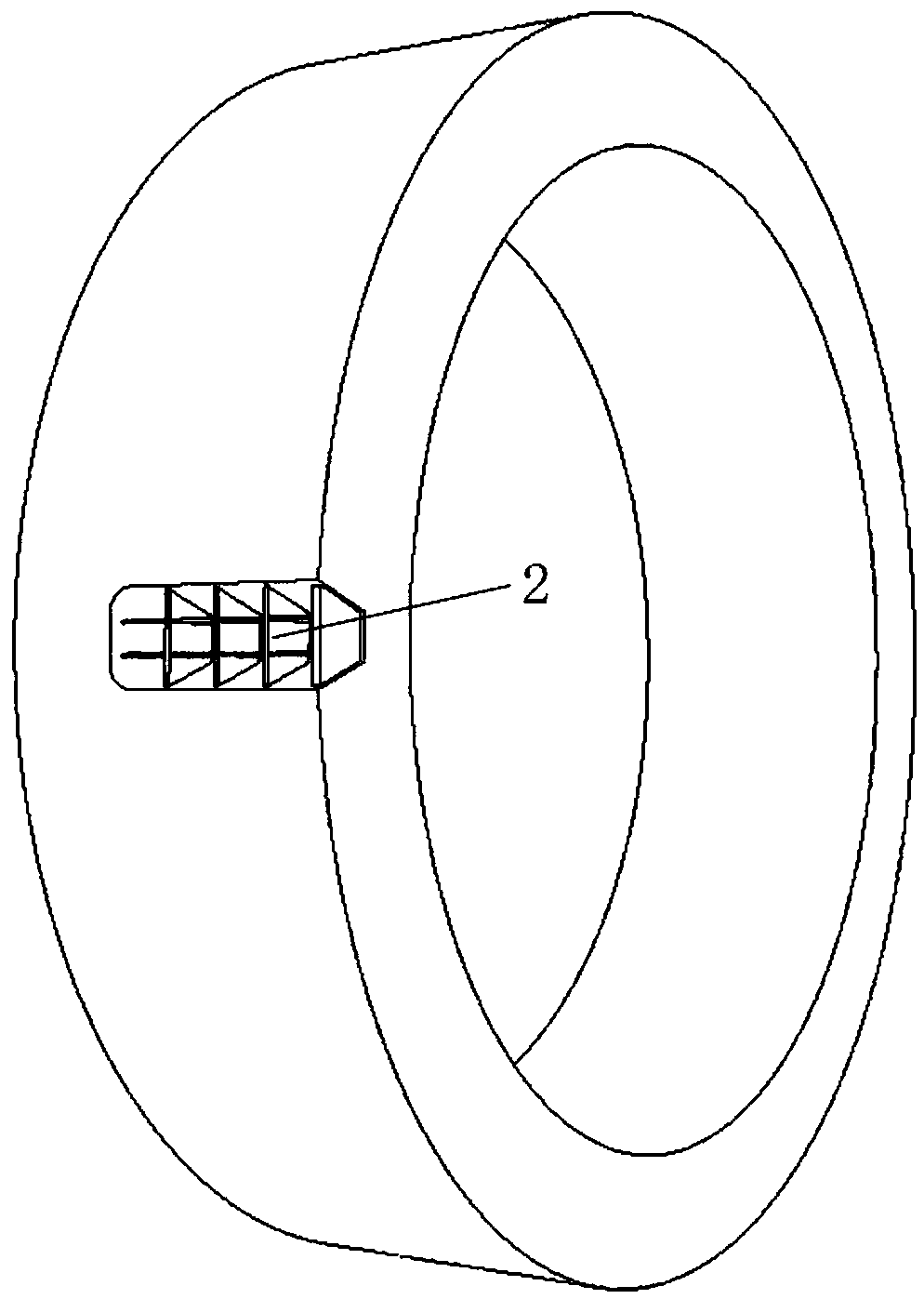
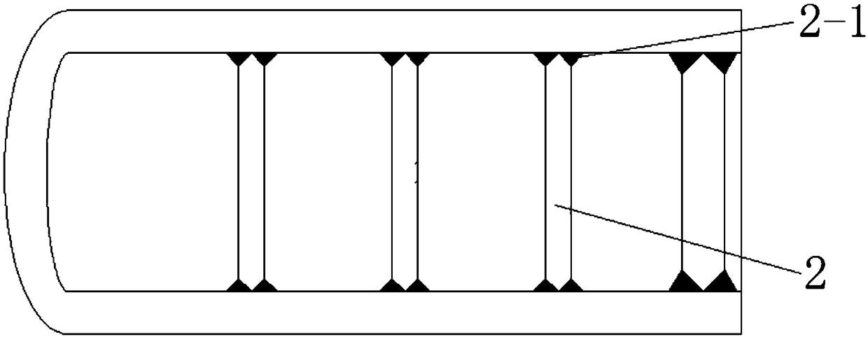
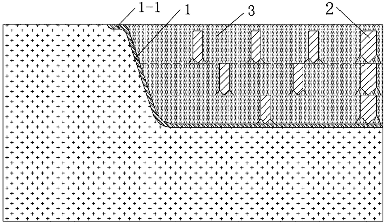
[0027] Specific embodiment 1: The welding structure of the welding groove of the metal defect of the steel casting in this embodiment is that the welding groove wall and the welding groove bottom of the welding groove are welded by welding deposited metal to form a layer of shell 1. The inner wall of the body 1 is provided with a plurality of built-in steel webs 2 at intervals along the longitudinal and transverse directions of the weld, and the inside of the welding groove with the shell structure is divided into multiple partition spaces by the built-in steel webs 2 .

[0028] In this embodiment, the specific plane geometry and outline dimensions of each built-in steel web should be determined according to the geometric factors of the actual excavation and welding grooves surveyed and drawn on site (non-standard), that is, the steel frame is built on the welding slope. The level area inside the mouth and the groove cross section of its location are set the same to achieve gaple...

Example Embodiment

[0029] Specific implementation manner 2: The reinforcement method of the welded structure of the metal defect digging and repairing groove of the steel casting in this embodiment is implemented in the following steps:

[0030] Step 1. Welding the shell structure: Along the welding groove wall and the welding groove bottom, a layer of the shell 1 which is completely fused with the welding groove wall and the groove bottom is welded with deposited metal in advance to obtain the shell 1 Body welding groove;

[0031] Step 2. Spatial arrangement of built-in steel webs: In the internal space enclosed by the shell structure in the welding groove, several rows and columns of built-in steel webs are arranged at intervals along the longitudinal and transverse directions of the weld. 2 , Weld connection between the inner side of the shell 1 and the contact surfaces of the longitudinally and horizontally arranged built-in steel webs 2 and the built-in steel webs 2 to form the inner side of the...

Example Embodiment

[0034] Specific embodiment three: this embodiment is different from specific embodiment two in that in step one, the metal defects inside the welding groove of the cut-and-repair welding are cleaned up in advance, the welding groove wall and the welding groove bottom are color-tested, and then polished Welding interface.


PUM

PropertyMeasurementUnit
Thicknessaaaaaaaaaa
Plate thicknessaaaaaaaaaa
Heightaaaaaaaaaa

Abstract

The invention relates to a welding structure of a metal defect digging-patching welding groove of a steel casting and a reinforcing method of the welding structure. By adoption of the welding structure of the metal defect digging-patching welding groove of the steel casting and the reinforcing method of the welding structure, the technical problems that during digging-patching welding of an existing large cast steel component, deformation of a welding structure is difficult to control, a repair welding area is likely to crack, and the structural stability and fatigue resistance of the weldingstructure cannot be guaranteed easily can be solved. The reinforcing method comprises the steps of first, welding a shell structure; second, arranging a plurality of rows and columns of multi-stage internal steel webs at intervals in the longitudinal and horizontal directions of a weld joint and the depth direction of the groove; third, filling welding deposited metal in a separated space of the welding groove; and fourth, conducting facing welding on the surface of the welding groove. According to the reinforcing method, a shell and rigid framework three-dimensional welding structural systemconstructed through welding can resist and disperse the shrinkage stress of weld joint metal, the welding deformation is effectively controlled, the stability of the welding structure is improved, propagation of fatigue cracks is changed, and accordingly, the propagation rate of the cracks is decreased.

Description

technical field [0001] The invention relates to a welding structure for digging and repairing welding grooves of metal defects in steel castings and a reinforcing method thereof, belonging to the technical field of welding structures. Background technique [0002] In medium carbon cast steel components such as tires and supporting wheels of cement rotary kilns in large-scale production equipment in the building materials industry or hollow shafts of cement mills, it is inevitable that some original pores, inclusions or loose structures generated during the casting process of the components remain. Casting defects. Therefore, in the long-term service process, the original casting defects are more likely to produce stress concentration (sharp angle effect) and local fatigue damage, which becomes the source of cracks. Under the continuous action of dynamic load and its alternating stress, the casting structure will further aggravate the fatigue damage of the metal, and its cra...

Claims


Application Information

Patent Timeline
IPC IPC(8): B23K33/00B23K31/02
CPCB23K31/02B23K33/00
Inventor 钟彬方洪渊陈波鲍爱莲查晓雄刘铁军赵云峰王玉银邓宏卫杜淼才维忠刘万辉赵春驰李洪斌史庆国林琳马千里钟雪霏周琦张海峰王晓楠黄垒
Owner 哈尔滨中正焊接技术开发有限公司
Why Eureka
Try Eureka