Method for preparing graduated color film through magnetron sputtering machine

A sputtering machine and color technology, used in sputtering coating, ion implantation coating, metal material coating process, etc., can solve the problems of less gradient color forms, inconvenient production, etc., to achieve stable refractive index and satisfy the market. Variety of effects with stable optical performance

Active Publication Date: 2018-12-18
SHENZHEN THREE BEAM COATING TECH CO LTD
View PDF7 Cites 33 Cited by
  • Summary
  • Abstract
  • Description
  • Claims
  • Application Information

AI Technical Summary

Problems solved by technology

[0007] However, the preparation of the gradient color disclosed above needs to block the first area and the second area separately, and also requires center symmetry, and the gradient color forms are relatively few, making it inconvenient

Method used


Image

  • Method for preparing graduated color film through magnetron sputtering machine
  • Method for preparing graduated color film through magnetron sputtering machine
  • Method for preparing graduated color film through magnetron sputtering machine

Examples


Embodiment 1

[0108] The sputtering machine used in this embodiment is a SWOS-2000H large magnetron sputtering machine.

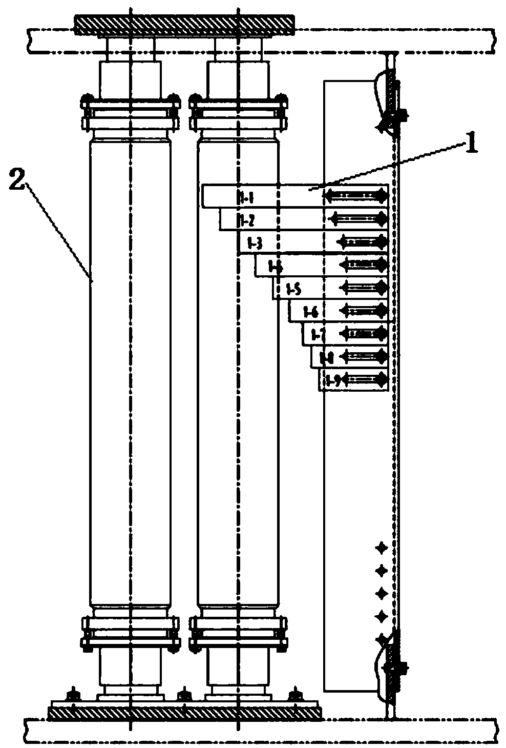
[0109] First, place the cleaned glass cover plate, that is, the workpiece 3, on the workpiece holder 4 of the sputtering machine, where the high refractive index target, the low refractive index target and the workpiece 3, and the shielding plate 1 are placed as Figure 3-5 As shown, the distance between the shielding plate 1 and the high refractive index target and the low refractive index target is 2 cm, and the distance between the shielding plate 1 and the workpiece 3 is 13 cm. 2 sets of shielding plates 1 shape are adopted Figure 7 The shapes shown are placed between the high refractive index target material and the low refractive index target material and the workpiece 3 respectively. Close the door and pump down to 5.0×10 -3 Pa, ion cleaning the workpiece 3 with the anode layer ion source for 10 minutes before coating.

[0110] After the ion cleaning of the anode lay...

Embodiment 2

[0117] First, place the cleaned glass cover plate, the workpiece 3, on the workpiece holder 4 of the sputtering machine, where the high extinction coefficient target material and the glass substrate are placed as Figure 7 As shown in the shielding plate 1, the distance between the shielding plate 1 and the target with high extinction coefficient is 4cm, the distance between the shielding plate 1 and the workpiece 3 is 11cm, and there is no shielding plate 1 between the other targets 2 and the workpiece 3. . The shape of the shield 1 is adopted Figure 7 The shape shown, close the door and pump to 5.0×10 -3 Pa, ion cleaning the workpiece 3 with the anode layer ion source for 10 minutes before coating.

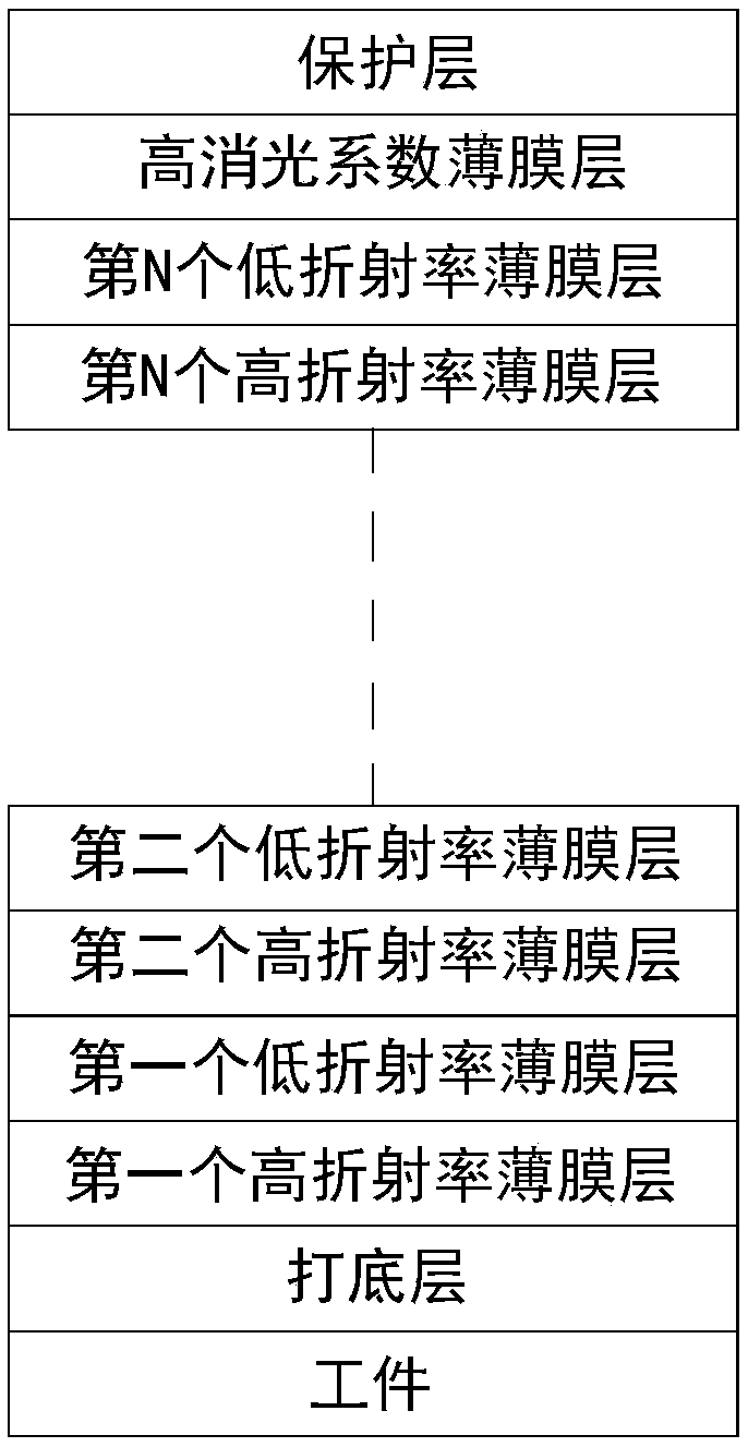
[0118] After the ion cleaning of the anode layer is completed, the coating is started. First, the bottom layer is plated on the workpiece 3, then the first high refractive index film is plated, then the first low refractive index film is plated, and then the second high refractive ...

Embodiment 3

[0122] First, place the cleaned glass cover plate, that is, the workpiece 3, on the workpiece holder 4 of the sputtering machine, and place it between the low refractive index target and the workpiece 3. Figure 8 As shown in the shielding plate 1, the distance between the shielding plate 1 and the low refractive index target is 5cm, the distance between the shielding plate 1 and the workpiece 3 is 10cm, and the other targets 2 and the workpiece 3 are not provided with a shielding plate 1. The shape of the shield 1 is adopted Figure 8 The shape shown, close the door and pump to 5.0×10 -3 Pa, ion cleaning the workpiece 3 with the anode layer ion source for 10 minutes before coating.

[0123] After the ion cleaning of the anode layer is completed, the coating is started. First, the bottom layer is plated on the workpiece 3, then the first high refractive index film is plated, then the first low refractive index film is plated, and then the second high refractive index film is plate...


PUM

PropertyMeasurementUnit
thicknessaaaaaaaaaa
thicknessaaaaaaaaaa
thicknessaaaaaaaaaa

Abstract

The invention discloses a method for preparing a graduated color film through a magnetron sputtering machine. The method comprises the following steps that S1, an optical film system is designed; S2,a baffle is designed, and the shape of the baffle is designed according to thickness change of an optical thin film structure simulated by software; S3, vacuum coating is conducted; and S4, color andoptical performance examination is conducted, the color LAB value, visible light reflectivity curve and visible light transmittance curve of a product obtained after vacuum coating are detected, if the test result is qualified, mass production preparation can be made, and if the test result is unqualified, operation returns to the step S1. A transition area of a graduated color film prepared withthe method is natural in gradual color change, the product color is easy to adjust, and graduated color films of different colors and visual effects can be prepared according to user preparations. Compared with electric beam evaporation deposition, a film layer prepared with the magnetron sputtering machine is compact in structure, the refractive index is stable, the film layer is more stable in optical performance, and thus color stability is better.

Description

Technical field [0001] The invention belongs to the technical field of vacuum coating, and particularly relates to a method for preparing a gradual color film by a magnetron sputtering machine applied to cover plates and back covers of electronic products such as mobile phones, tablet computers, smart watches and the like. Background technique [0002] With the advent of the fifth generation of mobile communication technology (5G), more and more mobile phone manufacturers use glass instead of metal as the back cover of their mobile phones. Glass is generally colorless and transparent, and silk screen ink is often needed to color it as a cover for mobile phones. But only silk screen printing ink, the color gloss is poor, and there is no metal texture of the metal back cover. With the diversification of market demand, the glass cover not only plays a protective role, but its function of beautifying decoration is also increasingly prominent. In order to increase the beauty of mobi...

Claims


Application Information

Patent Timeline
Patent Type & Authority Applications(China)
IPC IPC(8): C23C14/35C23C14/04C23C14/54C23C14/08C23C14/10
CPCC23C14/0015C23C14/0036C23C14/044C23C14/083C23C14/10C23C14/35C23C14/352C23C14/542
Inventor 郭杏元汤珅冯红涛战永刚
Owner SHENZHEN THREE BEAM COATING TECH CO LTD
Why Eureka
Try Eureka