Tool center point calibration circuit of welding robot

A tool center point and welding robot technology, which is applied in the direction of manufacturing tools, welding equipment, auxiliary welding equipment, etc., can solve the problems of difficult work, frequent movement of welding robots to find the center, etc.

Active Publication Date: 2018-12-21
浙江创利焊接科技股份有限公司
View PDF5 Cites 4 Cited by
  • Summary
  • Abstract
  • Description
  • Claims
  • Application Information

AI Technical Summary

Problems solved by technology

[0005] In view of the above situation, in order to overcome the defects of the prior art, the object of the present invention is to provide a tool center point calibration circuit of a welding robot, which effectively solves the problem that the welding robot frequently moves to find the center due to small deviations, and the work is difficult.

Method used


Image

  • Tool center point calibration circuit of welding robot
  • Tool center point calibration circuit of welding robot

Examples


Embodiment 1

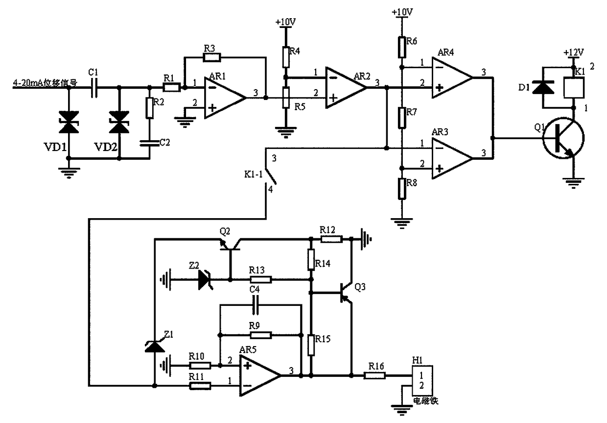
[0014] Embodiment 1, a tool center point calibration circuit of a welding robot, including a signal receiving circuit, a comparison switch circuit and a stable drive circuit, (here, the center point adjustment is divided into horizontal and vertical adjustments, and the adjustment methods are exactly the same), the The signal receiving circuit receives the horizontal or vertical 4-20mA displacement signal output by the tool center point detection circuit of the welding robot, and uses the transient suppression circuit composed of bidirectional diode VD1, bidirectional diode VD1 and capacitor C1 to suppress electromagnetic interference, composed of capacitor C2 and resistor R2 After further absorbing the electromagnetic interference, the RC absorbing circuit enters the current-voltage converter composed of the resistor R1, the resistor R3, and the operational amplifier AR1, and converts it into a 0-10V voltage signal. The subtraction circuit composed of amplifier AR2, resistor R...

Embodiment 2

[0016]Embodiment 2, on the basis of Embodiment 1, the signal receiving circuit receives the horizontal or vertical 4-20mA displacement signal output by the tool center point detection circuit of the welding robot, through the transient suppression diode VD1, capacitor C1, transient suppression The transient suppression circuit composed of diode VD2 suppresses electromagnetic interference, and the RC absorption circuit composed of resistor R2 and capacitor C2 further absorbs electromagnetic interference and releases it to the ground, so as to avoid the problem that the 4-20mA displacement signal is interfered by external signals during signal transmission. Then enter the current-voltage converter composed of resistor R1, resistor R3, and operational amplifier AR1, and convert it into a 0-10V voltage signal (the output voltage of the operational amplifier AR1 = the 4-20mA current at the inverting input terminal of the operational amplifier AR1 and the resistance value of the resis...

Embodiment 3

[0017] Embodiment 3, on the basis of Embodiment 1, the comparison switch circuit receives the 0-10V voltage signal output by the signal receiving circuit through the window circuit principle, and enters the threshold voltage of the non-inverting input terminal and the inverting input terminal of the operational amplifier AR2 (The voltage corresponding to the horizontal or vertical center point is 5V, provided by the voltage divider circuit composed of resistor R5 and resistor R4), perform subtraction, calculate the positive or negative deviation signal, and then enter the inverting input terminal of the operational amplifier AR3 and The non-inverting input terminal of the operational amplifier AR4 is compared with the threshold voltage of the non-inverting input terminal of the operational amplifier AR3 and the threshold voltage of the inverting input terminal of the operational amplifier AR3 (threshold voltage is provided by a voltage divider circuit composed of resistors R6, R...


PUM


Abstract

The invention discloses a tool center point calibration circuit of a welding robot. The tool center point calibration circuit includes a signal receiving circuit, a comparison switch circuit and a stable driving circuit. The signal receiving circuit transforms real-timely received 4-20 mA displacement signals into 0-10 V voltage signals, then the 0-10 V voltage signals enter a subtracter in the comparison switch circuit for subtracting, positive deviation signals or negative deviation signals are output, then the positive deviation signals or the negative deviation signals are compared and analyzed through a window comparison circuit composed of an operational amplifier AR3 and an operational amplifierAR4. When an allowable deviation range is exceeded by + / -3%, a high level is output, a relay K1 coil is energized, and the stable driving circuit receives the positive deviation signals or the negative deviation signals through a closed relay K1 normally open contact K1-1, and an operational amplifier AR5 is used for reversely amplifying the signals, the signals are subjected to feedback calibration through an audion Q2 and an audion Q3, and then the direction and magnitude of the current flowing through an electromagnet are controlled through a series resistor R16, so that the horizontal or vertical positive deviation signals or the horizontal or vertical negative deviation signals are adjusted; and the problems that due to small deviation, the welding robot moves frequently to find the center and the work is difficult are effectively solved.

Description

technical field [0001] The invention relates to the technical field of welding robots, in particular to a tool center point calibration circuit of a welding robot. Background technique [0002] After the welding robot is installed and before working, it is necessary to adjust the tool center point of the welding robot. The accuracy of the tool center point adjustment directly affects the welding accuracy of the welding robot. If the adjustment accuracy of the tool center point is low, it will cause the robot to Serious quality problems such as weld seam deviation occurred during the welding process. The prior art has disclosed an auxiliary device for adjusting the center point of a welding robot tool with the application number: 201710540632.0. The alignment needle on the welding gun of the welding robot is in contact with the bottom needle on the working platform of the welding robot, which improves the adjustment accuracy of the center point of the tool and also improves t...

Claims


Application Information

Patent Timeline
Patent Type & Authority Applications(China)
IPC IPC(8): B23K37/02
CPCB23K37/0258
Inventor 许少辉
Owner 浙江创利焊接科技股份有限公司
Why Eureka
Try Eureka