Sensor with three-aperture structure
A technology of sensors and apertures, which is applied in the field of sensors, can solve the problems of large spectral width and poor sensor performance, and achieve the effect of increasing wavelength resolution
- Summary
- Abstract
- Description
- Claims
- Application Information
AI Technical Summary
Problems solved by technology
Method used
Image
Examples
Embodiment 1
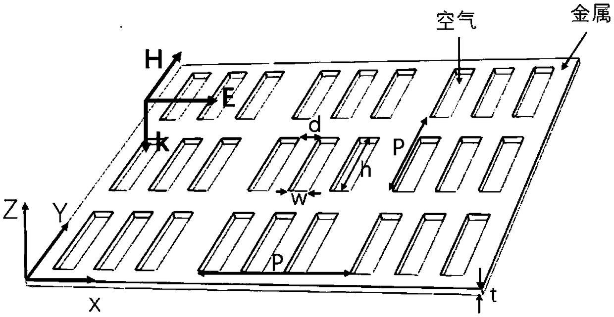
[0023] This embodiment provides a sensor with a three-hole slit structure, such as figure 1 , including a square metasurface, the material of the square metasurface is gold / silver / copper and other metals, and three identical and symmetrical rectangular holes are arranged in parallel in the square metasurface.
[0024] Among them, this embodiment is defined as follows:
[0025] The length of the rectangular holes is h, the width is w, and the distance between the rectangular holes is d. figure 1 It is a two-dimensional structure, the sensor side length of the three-hole slit structure is p, and the electromagnetic wave incident wave vector k is along the -z direction. The electromagnetic wave incident from the air unit forms the transmission situation of the wave in two different media. The electromagnetic wave is incident along the wave vector k, the electric field E is along the x-axis direction, and the magnetic field H is located on the yoz plane and is perpendicular to th...
Embodiment 2
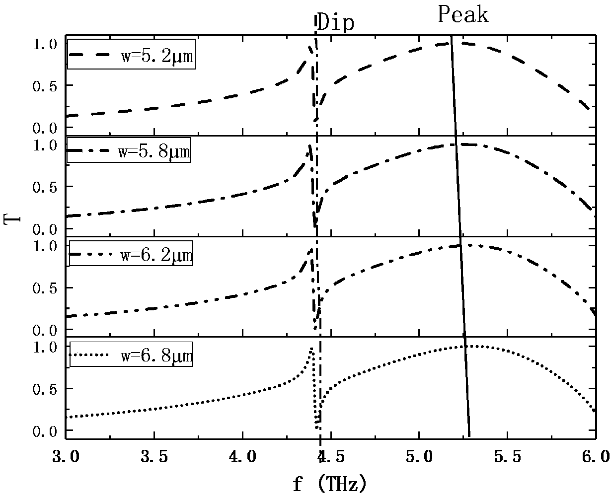
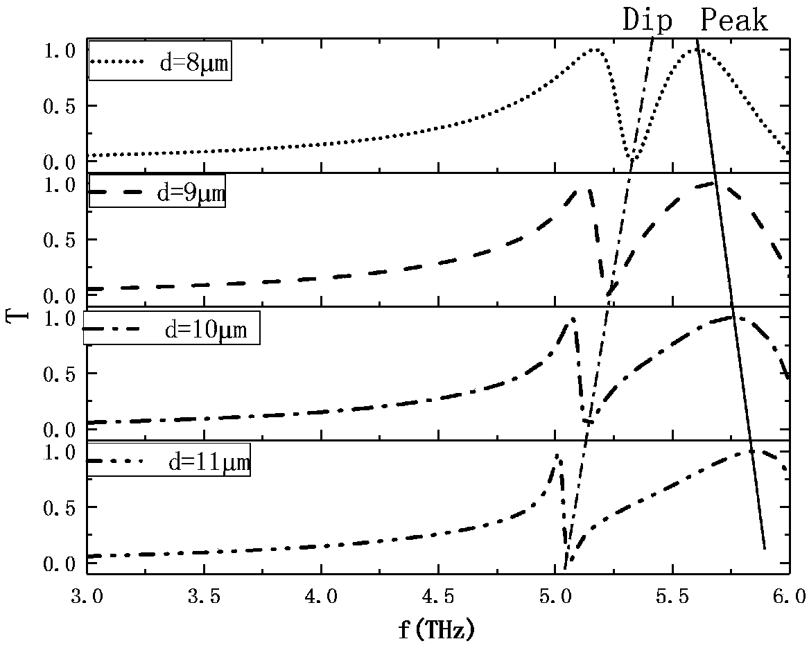
[0030] In this embodiment, a sensor model structure with a three-hole structure with parameters h=30 μm, w=6 μm, p=50 μm, and t=1 μm is established on the structure of embodiment 1, and the parameter d is simulated step by step.
[0031] Using simulation software based on finite element method to carry out numerical and analytical calculations, the results are as follows image 3 , is the relationship between transmission coefficient and frequency when the parameter d changes.
[0032] image 3 In , the relationship between the transmission coefficient and the frequency at different d is characterized: there is an obvious Fano resonance phenomenon at different d, the frequency of the transmission valley changes with the change of d, and the position of the transmission valley appears almost linear red shift (Fig. Indicated by Dip and black dotted line): That is, d increases, and the transmission valley frequency decreases.
[0033] Additionally, from image 3 It can be seen...
Embodiment 3
[0037] In this embodiment, a sensor model structure with a three-hole structure with parameters w=6 μm, d=10 μm, p=50 μm, and t=1 μm is established on the structure of embodiment 1, and the parameter h is simulated step by step.
[0038]Using simulation software based on finite element method to carry out numerical and analytical calculations, the results are as follows Figure 4 , which is the graph of transmission coefficient versus frequency.
[0039] Figure 4 The transmission coefficient versus frequency plots for different h are characterized. Such as Figure 4 , is the transmission characteristic relationship between h and the resonant frequency. With the change of h, the red shift of the transmission valley of the Fano resonance occurs (indicated by Dip and dotted line in the figure), and the red shift of the position of the transmission peak appears with the increase of h (indicated by Peak and the solid line in the figure), the above rule In turn, it shows that t...
PUM
| Property | Measurement | Unit |
|---|---|---|
| Length | aaaaa | aaaaa |
| Width | aaaaa | aaaaa |
Abstract
Description
Claims
Application Information
 - R&D
- Intellectual Property
- Life Sciences
- Materials
- Tech Scout
- Unparalleled Data Quality
- Higher Quality Content
- 60% Fewer Hallucinations
Browse by: Latest US Patents, China's latest patents, Technical Efficacy Thesaurus, Application Domain, Technology Topic, Popular Technical Reports.
© 2025 PatSnap. All rights reserved.Legal|Privacy policy|Modern Slavery Act Transparency Statement|Sitemap|About US| Contact US: help@patsnap.com


