
Identification system based on communication beam orbital angular momentum mode of digital micro-mirror

A technology of orbital angular momentum and identification system, which is applied in the transmission monitoring/testing/fault measurement system, photometry using electric radiation detectors, etc. It can solve the problems of difficult to realize OAM beam pattern recognition, OAM beam crosstalk, crosstalk is difficult to eliminate, etc. problem, to achieve the effect of simple structure, cheap price and simple operation

Pending Publication Date: 2018-12-21
SOUTH CENTRAL UNIVERSITY FOR NATIONALITIES
View PDF5 Cites 7 Cited by
  • Summary
  • Abstract
  • Description
  • Claims
  • Application Information

AI Technical Summary

Problems solved by technology

The limited use of interference or diffraction recognition methods is difficult to solve the problem of multi-mode OAM beam pattern recognition. The main reason is that there is serious crosstalk between different modes of OAM beams when the multiplexed beams are interfering or diffracting, and this crosstalk Difficult to eliminate
The idea of ​​the above method is simple, and the construction of the actual link is relatively simple, but only one OAM beam can be recognized at the same time, and it is difficult to realize the pattern recognition of the multi-mode multiplexed OAM beam

Method used


Image

  • Identification system based on communication beam orbital angular momentum mode of digital micro-mirror
  • Identification system based on communication beam orbital angular momentum mode of digital micro-mirror
  • Identification system based on communication beam orbital angular momentum mode of digital micro-mirror

Examples


Embodiment Construction

[0042] The present invention will be further described below in conjunction with the drawings and embodiments.

[0043] 1. System

[0044] 1. Overall

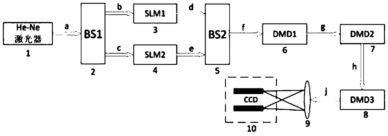
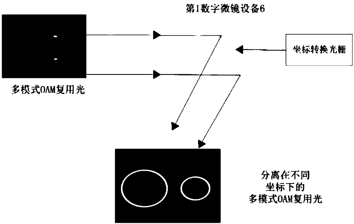
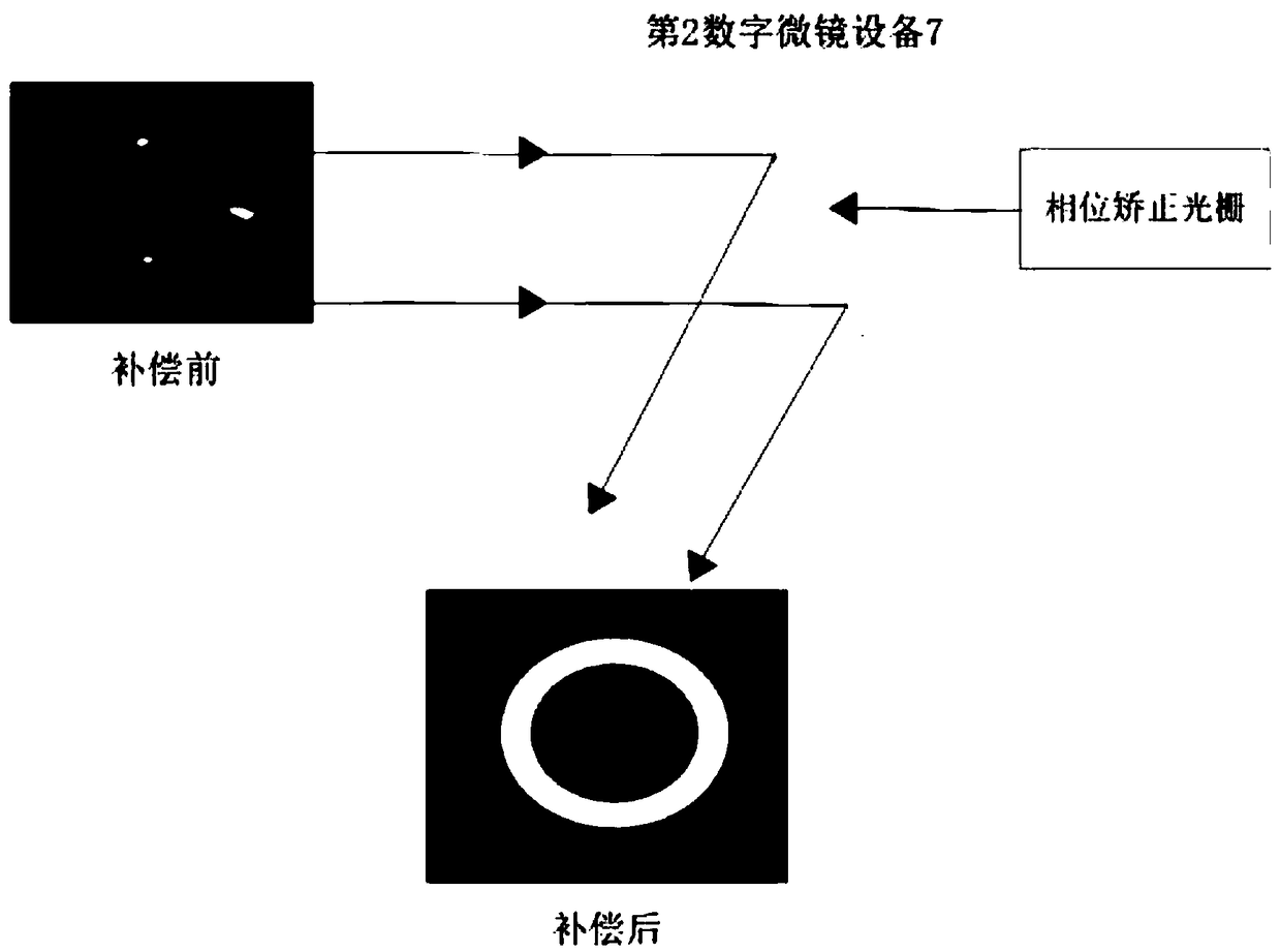
[0045] Such as figure 1 , This system includes He-Ne laser 1, first beam splitter 2, first spatial light modulator 3, second spatial light modulator 4, second beam splitter 5, first digital micromirror device 6, second Digital micromirror device 7, the third digital micromirror device 8, lens 9 and charge coupled camera 10;

[0046] Its connected relationship is;

[0047] The He-Ne laser 1 and the first beam splitter 2 communicate back and forth, and the first beam splitter 2 communicates with the first spatial light modulator 3 and the second spatial light modulator 4, and the first spatial light modulator 3 and the second spatial light modulator The spatial light modulator 4 is respectively connected with the second beam splitter 5, the second beam splitter 5, the first digital micromirror device 6, the second digital micromirror dev...


PUM


Abstract

The invention discloses an identification system based on a communication beam orbital angular momentum mode of a digital micro-mirror, and relates to an optical communication technology. The identification system is as follows: a He-Ne laser is communicated with the front and back of a first beam splitter; the first beam splitter is respectively communicated with a first spatial light modulator and a second spatial light modulator; the first spatial light modulator and the second spatial light modulator are respectively communicated with a second beam splitter; and the second beam splitter, afirst digital micro-mirror device, a second digital micro-mirror device, a third digital micro-mirror device, a lens and a charge coupled camera are communicated in turn. According to the identification system based on the communication beam orbital angular momentum mode of the digital micro-mirror, separation and identification of a multiplexed multi-mode orbital angular momentum beam are realized using the digital micro-mirror device; distortion correction of each light spot phase is realized utilizing a phase compensation mechanism; and mode recognition of orbital angular momentum under any mode is realized, and simultaneous mode recognition of the multi-mode orbital angular momentum beam is overall realized utilizing a diffraction identification mechanism.

Description

Technical field [0001] The invention relates to optical communication technology, in particular to a digital micromirror-based recognition system for the orbital angular momentum pattern of a communication beam. Background technique [0002] Orbital Angular Momentum (OAM) beam is also called vortex beam, which means that its wavefront contains a spiral phase structure, and the light field intensity distribution presents the characteristics of a ring structure; the spiral phase function of OAM beam is expressed as exp(ilθ), where θ is the angular coordinate, l is the azimuth index, and the magnitude of l determines the topological charge of the OAM beam. Theoretically, the topological charge of the OAM beam can be changed arbitrarily, and different OAM states are orthogonal to each other. OAM beam has these unique characteristics, so it has great potential application value in optical operation, remote sensing technology, optical tweezers, quantum information technology and free ...

Claims


Application Information

Patent Timeline
Patent Type & Authority Applications(China)
IPC IPC(8): G01J1/42H04B10/07
CPCH04B10/07G01J1/42
Inventor 杨春勇邹文康兰悦侯金钟志有陈少平
Owner SOUTH CENTRAL UNIVERSITY FOR NATIONALITIES
Learn More