An infrared thermal imager autofocus system and method with temperature compensation

An infrared thermal imager and temperature compensation technology, which is applied in the parts of TV systems, image communication, parts of color TV, etc. failure, etc.

Active Publication Date: 2020-07-07
KUNMING INST OF PHYSICS
View PDF4 Cites 0 Cited by
  • Summary
  • Abstract
  • Description
  • Claims
  • Application Information

AI Technical Summary

Problems solved by technology

Usually, even if the automatic focusing method suitable for visible light can realize the automatic focusing method functionally, the long focusing stroke will lead to real-time performance degradation, which cannot meet the requirements of engineering realization.
[0005] 3. The parfocality of the optical system of the infrared thermal imaging camera drifts greatly with temperature. If it is not compensated before auto-focusing, it is difficult for the usual auto-focusing method to traverse the entire focus under full-temperature work in a short time. journey
For the second method of artificially increasing the sampling window intervention of the image definition evaluation function, on the one hand, adding manual intervention loses the meaning of the automatic focusing method; , even if manual intervention actively participates, there is no way to start, and its method is still ineffective
The above two improved automatic focusing methods ignore the influence of ambient temperature on the parfocality of the infrared thermal imager, and can only be more suitable for laboratory verification, and cannot provide a method for engineering realization

Method used


Image

  • An infrared thermal imager autofocus system and method with temperature compensation
  • An infrared thermal imager autofocus system and method with temperature compensation
  • An infrared thermal imager autofocus system and method with temperature compensation

Examples


Embodiment 1

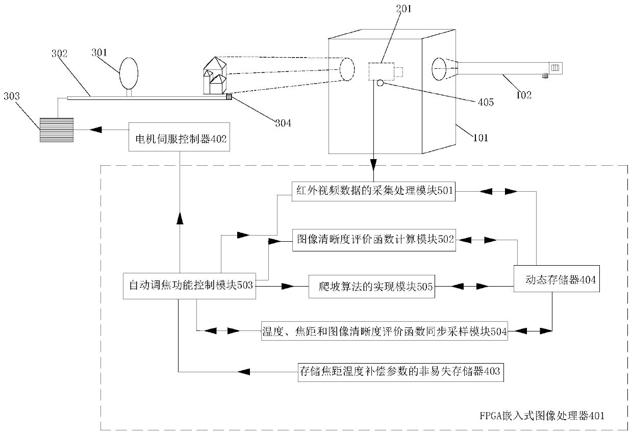
[0056] An automatic focusing system of an infrared thermal imager with temperature compensation, comprising: a high and low temperature environment experiment box 101, a collimator 102, an infrared thermal imager 201, a focusing mirror 301, a sliding screw rod 302 for the focusing mirror, and a focusing motor 303, screw position sensor 304, FPGA embedded image processor 401, motor servo controller 402 and thermal imager complete machine temperature sensor 405;

[0057] The infrared thermal imager 201 is placed in the high and low temperature environment test box 101, and the two sides of the high and low temperature environment test box 101 are provided with openings as observation windows. to the scene;

[0058] The control terminal of the motor servo controller 402 is connected with the focus motor 303, and is used to control the work of the focus motor 303;

[0059] The power output end of the focusing motor 303 links to each other with the sliding screw rod 302 of the foc...

Embodiment 2

[0080] An automatic focusing system of an infrared thermal imager with temperature compensation, comprising: a high and low temperature environment experiment box 101, a collimator 102, an infrared thermal imager 201, a focusing mirror 301, a sliding screw rod 302 for the focusing mirror, and a focusing motor 303, screw position sensor 304, FPGA embedded image processor 401, motor servo controller 402 and thermal imager complete machine temperature sensor 405;

[0081] The infrared thermal imager 201 is placed in the high and low temperature environment test box 101, and the two sides of the high and low temperature environment test box 101 are provided with openings as observation windows. to the scene;

[0082] The control terminal of the motor servo controller 402 is connected with the focus motor 303, and is used to control the work of the focus motor 303;

[0083] The power output end of the focusing motor 303 links to each other with the sliding screw rod 302 of the foc...


PUM


Abstract

The invention relates to an infrared thermal imager automatic focusing system and method with temperature compensation, belonging to the technical field of infrared thermal imaging processing. The system includes a high and low temperature environmental experiment box, a collimator, an infrared thermal imager, a focusing mirror, a sliding screw for the focusing mirror, a focusing motor, a screw position sensor, an FPGA embedded image processor, a motor servo controller and Thermal imager complete machine temperature sensor and other components; the present invention aims at the thermal imager complete system with large zoom ratio and long focal length optical system, compresses the autofocus search range, strengthens the boundary constraints of the climbing algorithm, and improves the automatic The reliability and real-time performance of the focusing method have significant advantages in engineering implementation.

Description

technical field [0001] The invention belongs to the technical field of infrared thermal imaging processing, and in particular relates to an automatic focusing system and method of an infrared thermal imager with temperature compensation. Background technique [0002] As far as the autofocus method and implementation are concerned, mature applications in visible light imaging systems are not uncommon. However, compared with visible light imaging systems, the size, structure and quality of infrared thermal imager optical systems make conventional autofocus methods difficult to apply Infrared camera. The infrared camera has the following characteristics: [0003] 1. The signal response rate of the infrared sensor is low and the noise is large. In order to obtain better quality infrared video, a larger clear aperture is required to obtain more infrared radiation, which leads to a larger volume and quality of the optical system , causing the movement of the matching focusing se...

Claims


Application Information

Patent Timeline
Patent Type & Authority Patents(China)
IPC IPC(8): H04N5/33H04N5/232
CPCH04N5/33H04N23/67
Inventor 杨瑞宇樊佩琦吴诚苏兰洪闻青陈洁王晓东苏俊波柯伟曾兴荣田桂平周春芬杨波胡志斌王杰赵灿兵向麟槐张润琦陈树刚粟宇路陈大乾刘鹏李谦李贺禹
Owner KUNMING INST OF PHYSICS
Why Eureka
Try Eureka