
Glass filler-reinforced solid resin

A glass filler and solid resin technology, the optical properties of the material-reinforced resin have not yet been reached, and the rate is in the field of the glass filler, which can solve the problems such as the optical properties not reaching an acceptable level, and achieve good optical properties and high performance. Transmittance, high brightness effect

Inactive Publication Date: 2018-12-21
SABIC GLOBAL TECH BV
View PDF4 Cites 0 Cited by
  • Summary
  • Abstract
  • Description
  • Claims
  • Application Information

AI Technical Summary

Problems solved by technology

[0003] Although filler-reinforced transparent resins such as glass fiber-reinforced transparent resins can be used to produce various products requiring good optical properties such as high visible light transmission and low haze, simple and widely used processing methods such as injection molding, The stated optical properties of filler-reinforced resins produced by extrusion and thermocompression have not reached acceptable levels for glass and unfilled transparent resin replacement

Method used


Image

  • Glass filler-reinforced solid resin
  • Glass filler-reinforced solid resin
  • Glass filler-reinforced solid resin

Examples


Embodiment 1

[0082] Example 1. Formation of samples

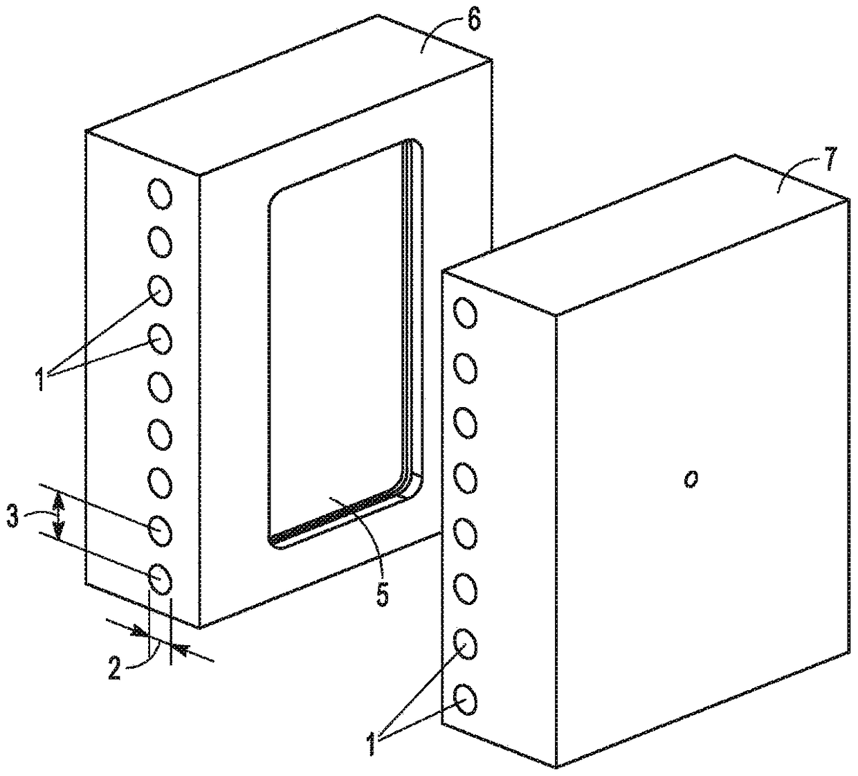
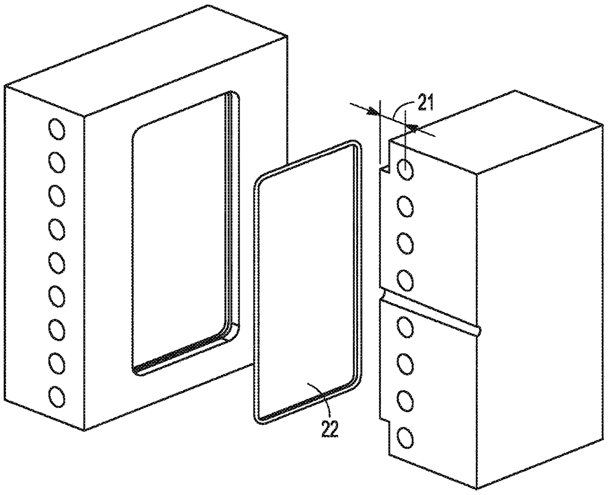
[0083] Double-sided dynamic temperature-controlled injection molding tools are machined using a grinder or end-mill, polishing wetstone (rough to smooth (from #1500 to #3000), then polished with Sandpaper was polished from (coarse to smooth (from #2000 to #3000)), and finally Diamond Compound #2 from Universal Superabrasives, USA. The final polished tool had about R a 6.5 nm smoothness. The tools such as figure 1 Shown in , with sides 6 and 7. The diameter 2 of the heating / cooling channel 1 is about 8 mm. The center of the heating / cooling channel 1 is located approximately 8 mm from the tool core surface 5 . The distance 3 between the heating / cooling channels is about 16 mm. figure 2 A cross-section of the molding tool is shown showing the molded part 22 . Said distance 21 is about 8 mm.

[0084] The injection molding tool was used for bisphenol-A based polycarbonate (refractive index 1.586) and poly(1,4-cyclohexylidenecycloh...

Embodiment 2

[0086] Example 2. Characterization of samples

[0087]Total transmittance, diffuse transmittance and haze were measured using a HM-150 from Murakami Color Research Laboratory, all using a halogen D65 (CIE standard) light source from 380 nm to 780 nm. Brightness was measured with an SR-3A supplied by Topcon, which irradiates the sample onto a white board using a xenon light source, and detects reflected light from the sample and from the white board through the sample. Surface roughness was measured using a Contour Elite I from Bruker.

[0088] Figure 4A The diagram illustrates how to communicate with the Lexan TM Total transmittance at 380-780 for samples 1-3 at 1.5 mm thickness compared to LS1. The overall transmittance was improved for samples 2 and 3, with double-sided heating and cooling of sample 3 providing the best results. Figure 4B The graph illustrates the total transmission of Sample 3 at thicknesses of 1.5mm, 2.5mm and 3.5mm. As the thickness decreases, th...

Embodiment approach

[0103] The following exemplary embodiments are provided herein, the numbering of which should not be construed as indicating a level of importance:


PUM

PropertyMeasurementUnit
luminanceaaaaaaaaaa
luminanceaaaaaaaaaa
surface roughnessaaaaaaaaaa

Abstract

Glass filler-reinforced solid resins and methods of making the same. The method includes contacting a flowable resin composition and a tool. The flowable resin composition includes a flowable resin and glass filler. The method includes molding or forming the flowable resin composition with the tool. The method includes curing the flowable resin composition, to form the glass filler-reinforced solid resin. Substantially all the surface of the tool that contacts the flowable resin composition during the curing thereof has a surface roughness Ra of about 2 microns or less. A refractive index of the glass filler is within about 0.100 of a refractive index of a cured product of the flowable resin in the glass filler-reinforced solid resin.

Description

[0001] Citations to related applications [0002] This application claims the benefit of priority to U.S. Provisional Patent Application Serial No. 62 / 302,279, filed March 2, 2016, the disclosure of which is incorporated herein by reference in its entirety. Background technique [0003] Although filler-reinforced transparent resins such as glass fiber-reinforced transparent resins can be used to produce various products requiring good optical properties such as high visible light transmission and low haze, simple and widely used processing methods such as injection molding, The optical properties of filler-reinforced resins produced by extrusion and thermoforming have not yet reached acceptable levels for glass and unfilled transparent resin replacement. Contents of the invention [0004] In various embodiments, the present invention provides methods of making glass filler-reinforced solid resins. The method includes contacting a flowable resin composition and a tool. The ...

Claims


Application Information

Patent Timeline
Patent Type & Authority Applications(China)
IPC IPC(8): C08K3/40C08K7/14C08K7/20C08J3/20C08J5/04C08L69/00C08J5/18
CPCC08K3/40C08K7/14C08K7/20C08L69/00C08L67/02B29K2509/08B29C45/372B29C45/0013C08L101/00B29C70/58B29K2067/00B29K2069/00B29K2995/0031
Inventor 崔钟民安娜荣王梁
Owner SABIC GLOBAL TECH BV
Learn More