Surface treatment material, production method thereof, and component formed using surface treatment material

A surface treatment and manufacturing method technology, applied in thin material treatment, chemical instruments and methods, metal material coating technology, etc., can solve problems such as cracks and achieve high long-term reliability

Inactive Publication Date: 2018-12-21
FURUKAWA ELECTRIC CO LTD
View PDF20 Cites 3 Cited by
  • Summary
  • Abstract
  • Description
  • Claims
  • Application Information

AI Technical Summary

Problems solved by technology

For these applications, there is a problem that cracks will occur in the case of the thickness of the nickel-based plating that has been used conventionally to suppress the diffusion of zinc.

Method used


Image

  • Surface treatment material, production method thereof, and component formed using surface treatment material
  • Surface treatment material, production method thereof, and component formed using surface treatment material
  • Surface treatment material, production method thereof, and component formed using surface treatment material

Examples


Embodiment

[0127] Next, the surface treatment material of the present invention was produced as a trial and its performance was evaluated, which will be described below.

[0128] (Invention Examples 1 to 21)

[0129] On the aluminum base material (0.2mm×30mm×30mm in size) shown in Table 12, the electrolytic degreasing process was carried out according to the above conditions. The indicated zinc replacement treatment conditions were followed by zincate treatment constituting the above-mentioned second surface activation treatment, and partial dissolution was performed after forming a zinc-containing thick film layer with the thickness shown in Table 12, thereby forming a zinc-containing thick film layer with the thickness shown in Table 12. layer. For Inventive Examples 5, 12 to 14 and 21, the second surface activation treatment was not performed (the zinc-containing layer was not formed.). Next, for Invention Examples 1 to 21 (except Invention Example 14.), use an acid solution contain...

example 1~4

[0133] For Conventional Examples 1 to 4, the electrolytic degreasing process was carried out under the above conditions on the aluminum substrate (dimensions 0.2mm×30mm×30mm) shown in Table 13, and then, for Conventional Examples 1 and 2, by performing the conventional Zinc replacement treatment (zincate treatment) to form a zinc-containing layer with the thickness shown in Table 12. In addition, in Conventional Example 3, the conventional zinc replacement treatment (zincate treatment) was not performed, and in Conventional Example 4, immersion treatment was performed in a nickel plating solution containing hydrofluoric acid and a nickel salt shown in Table 13. Thereafter, in Conventional Examples 1 to 4, the first surface activation treatment was not performed, and the above-mentioned surface treatment film formation step was performed to form a surface treatment film consisting of two metal layers with the thicknesses shown in Table 12. , and make surface treatment materials...


PUM

PropertyMeasurementUnit
thicknessaaaaaaaaaa
thicknessaaaaaaaaaa
thicknessaaaaaaaaaa

Abstract

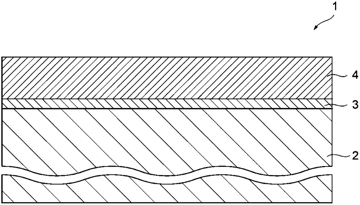
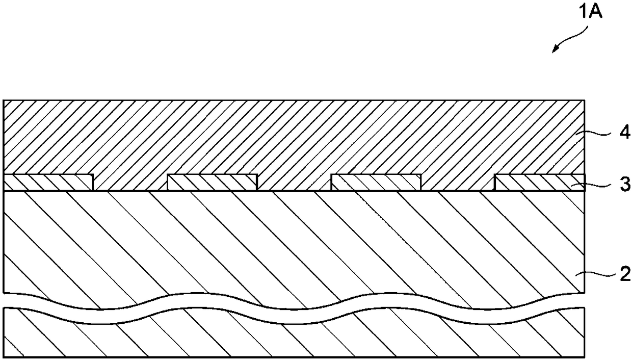
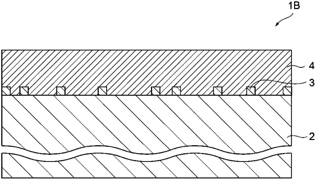
The present invention provides a surface treatment material or the like that exhibits suppressed deterioration of the characteristics of the surface of a surface treatment coating, particularly the characteristics of contact resistance and solder wettability when used in a high temperature (200 DEG C, for example) environment, without adversely affecting bending workability. The surface treatmentmaterial (1) according to the present invention has a conductive substrate (2) and a surface treatment coating (4) comprising at least one metal layer formed on the conductive substrate (2). The surface treatment coating (4) is a plating coating, is formed on the entire surface of the conductive substrate (2) or a portion thereof via a zinc-containing layer (3) having a thickness of 50 nm or lessand having zinc as a main component, or is formed on the conductive substrate (2) without using the zinc-containing layer (3), and has a bonding area percentage of 85% or more where the bonding area is the test area as measured using the tape test method stipulated by JIS H8504:1999.

Description

technical field [0001] The present invention relates to a surface treatment material, a method for producing the same, and an element formed using the surface treatment material. In particular, the present invention relates to a technique for forming a dense plated film on a conductive substrate mainly composed of a base metal with a high ionization tendency. , good adhesion and easy formation of a surface treatment coating composed of at least one metal layer. Background technique [0002] Metal materials such as copper, copper alloys, iron, and iron alloys are widely used as conventional materials to be plated (conductive substrates) for forming electrical contacts and the like from the viewpoint of low cost and excellent relative characteristics. In particular, such metal materials have good electrical conductivity and processability, are relatively easy to obtain, and are easy to be coated on the surface, and have a surface with excellent coating adhesion, etc. Therefore...

Claims


Application Information

Patent Timeline
Patent Type & Authority Applications(China)
IPC IPC(8): C25D5/44B32B15/01C23C18/18C25D5/30H01R13/03
CPCB32B15/01H01R13/03C25D5/44C23C18/54C25D3/12C25D5/10C25D5/12C23C18/1651C23C18/1831C23C18/1841C25D7/00C23C18/1653C23C18/1689C23C18/1848C23C18/18C23C30/00C23C18/42C23C18/165C23C18/38C23C18/1827C23C18/1837C23C30/005C23C18/1803C23C18/1824C23C18/31C23C18/32Y10T428/12743Y10T428/12868Y10T428/12799H01R13/04Y10T428/12896Y10T428/12757Y10T428/12736Y10T428/12792Y10T428/12889Y10T428/24967Y10T428/12931Y10T428/12715Y10T428/12903Y10T428/12708Y10T428/2495H01R13/02Y10T428/12861Y10T428/12944Y10T428/26Y10T428/24959Y10T428/12875Y10T428/12722Y10T428/12937Y10T428/12882Y10T428/1291Y10T428/265Y10T428/263Y10T428/264
Inventor 山内美保北河秀一小林良聪
Owner FURUKAWA ELECTRIC CO LTD
Why Eureka
Try Eureka