Physical cell disrupting microstructure device and cell disrupting and processing method thereof

A cell fragmentation and microstructure technology, applied in biochemical equipment and methods, methods for stress-stimulated microbial growth, biochemical cleaning devices, etc. fragmentation and other problems, to achieve the effect of promoting a highly integrated microfluidic system, avoiding excessive fragmentation, and uniform cell fragmentation

Active Publication Date: 2018-12-25
SOUTHEAST UNIV
View PDF4 Cites 0 Cited by
  • Summary
  • Abstract
  • Description
  • Claims
  • Application Information

AI Technical Summary

Problems solved by technology

[0005] 1. The crushing system itself is too large to be combined with the microfluidic system
[0006] 2. Introduce chemical impurities, contaminate cell fragments, and affect the follow-up operation of the experiment
[0007] 3. The degree of cell fragmentation cannot be adjusted, which may cause excessive or insufficient fragmentation of cells
[0008] 4. The broken structure is complex and difficult to process

Method used


Image

  • Physical cell disrupting microstructure device and cell disrupting and processing method thereof
  • Physical cell disrupting microstructure device and cell disrupting and processing method thereof
  • Physical cell disrupting microstructure device and cell disrupting and processing method thereof

Examples


Embodiment 1

[0056] The pipe diameter of the first cell suspension input tube unit of the present invention is 5 microns, and the tube diameter of the second cell suspension input tube unit is 100 microns. The purpose is to break up the cell suspension into particles with a particle size of 5 microns and hit them against the breaking plate. The pipe diameter of the first high-speed carrier gas input pipe unit is 50 microns, and the pipe diameter of the second carrier gas input pipe unit is 100 microns, in order to increase the output flow rate of nitrogen. Because of the small size of the structure, the structure can be processed and integrated into a microfluidic chip.

Embodiment 2

[0058] The pipe diameter of the first cell suspension input tube unit of the present invention is 5 microns, and the tube diameter of the second cell suspension input tube unit is 100 microns. The purpose is to break up the cell suspension into particles with a particle size of 5 microns and hit them against the breaking plate. The pipe diameter of the first high-speed carrier gas input pipe unit is 50 microns, and the pipe diameter of the second carrier gas input pipe unit is 100 microns, in order to increase the output flow rate of nitrogen. Add a filter device at the output end of the crushing chamber to filter out DNA or RNA in the cell residue, and then flow the output liquid into the PCR instrument for replication. This implementation case can simplify the experimental steps and save experimental operation time.

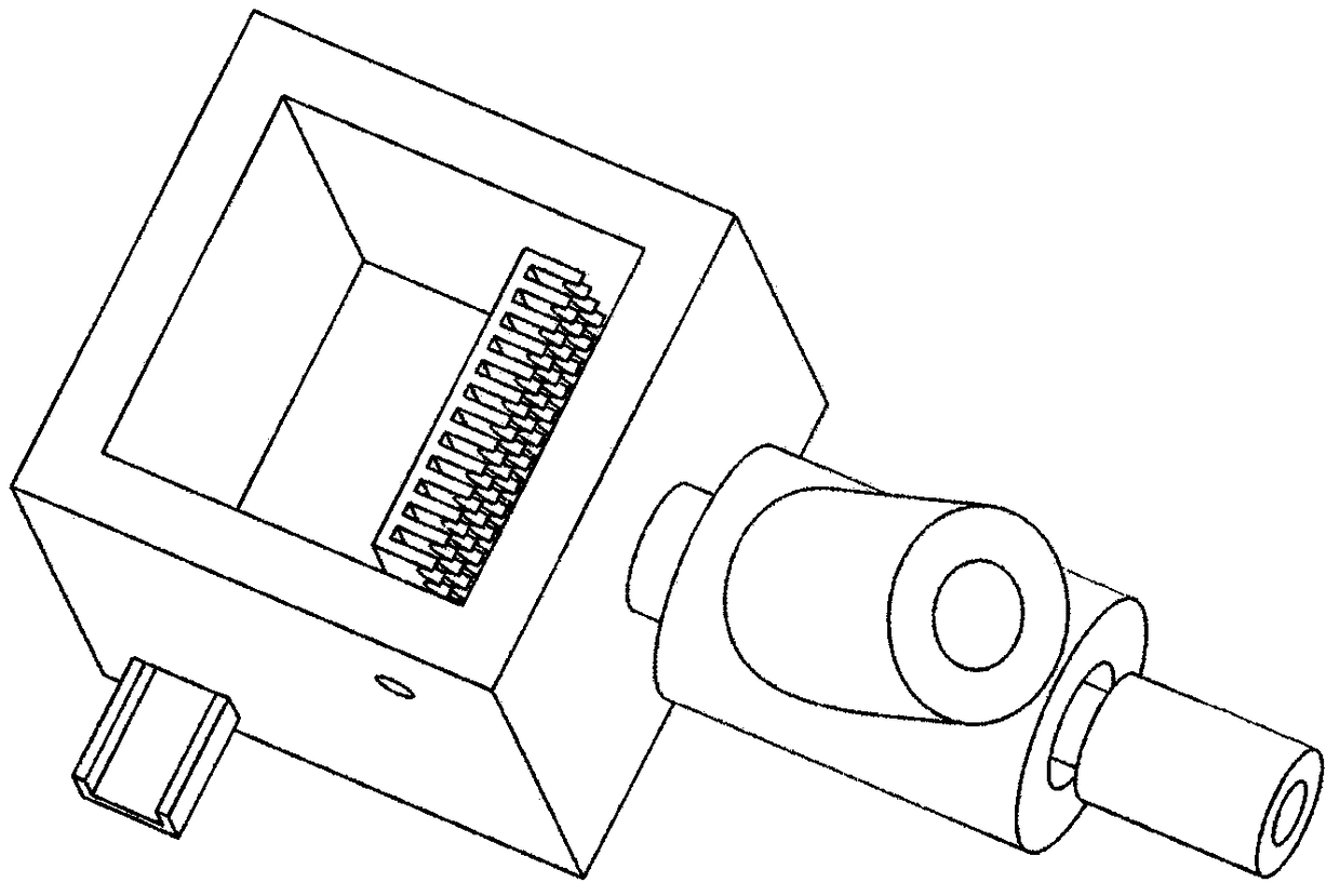
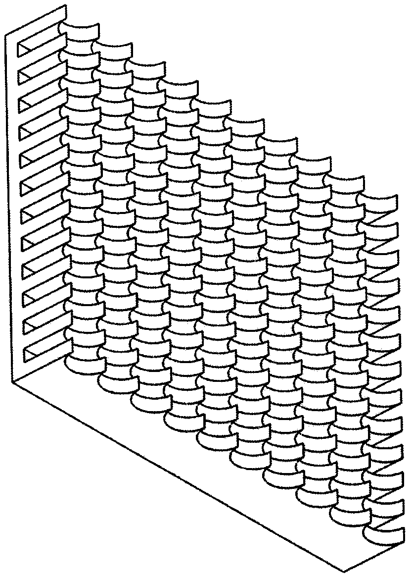
[0059] As a further preferred solution of the technical solution of the present invention, the piercing structure on the crushing plate is a cone array structu...


PUM

PropertyMeasurementUnit
diameteraaaaaaaaaa
diameteraaaaaaaaaa
particle diameteraaaaaaaaaa

Abstract

The invention discloses a physical cell disrupting microstructure device which structurally comprises a nitrogen input pipeline, a cell suspension solution input pipeline, a disrupting chamber and a disrupting plate. The disrupting chamber and a runner connection with the disrupting chamber are processed by an organic polymer molding method, the disrupting chamber is sealed by a thermal bonding method, and other portions are connected in a welded manner. A cell disrupting system ruptures cells by a physical collision method, and target components in the cells are extracted, so that next experiment is implemented. Cell suspension solution passes a pipeline outlet by a spray shape, and the diameter of spray particles is about 5 micrometers. The flow speed of nitrogen carried at high speed is200-300m / s, and the spray-shaped macro-particles are conveyed into the disrupting chamber and impact the disrupting plate at high speed, so that the cells are disrupted. Cell residue is collected inthe disrupting chamber and outputted from an outlet, and a follow-up micro-fluidic control experiment is implemented.

Description

technical field [0001] The invention relates to a microstructure device for physical cell crushing and a cell crushing and processing method thereof, belonging to the field of cell crushing. Background technique [0002] Microfluidic chip (microfluidic chip) is currently a hot field in the development of Miniaturized Total Analysis Systems. Its goal is to integrate the functions of the entire laboratory, including sampling, dilution, reagent addition, reaction, separation, detection, etc. There has been no systematically feasible cell disruption solution for microfluidic chips. Common cell disruption techniques can be divided into mechanical and non-mechanical methods. Mechanical methods include: [0003] High-pressure homogenization (homogenization), oscillating bead crushing (Skaking Bead), high-speed stirring bead grinding and crushing (fine grinding), ultrasonic crushing (ultrasonication); non-mechanical methods include: osmotic shock crushing (osmotic shock) ), Freez...

Claims


Application Information

Patent Timeline
Patent Type & Authority Applications(China)
IPC IPC(8): C12M1/00C12M1/33
CPCC12M23/16C12M35/04
Inventor 沙菁傅方舟陈云飞孙倩怡张志诚
Owner SOUTHEAST UNIV
Why Eureka
Try Eureka