
A time-to-digital conversion circuit based on multiple sampling

A technology of time-to-digital conversion and multiple sampling, applied in time-to-digital converter, analog/digital conversion calibration/test, analog/digital conversion, etc. Measurement accuracy, effect of simplified circuit structure

Active Publication Date: 2018-12-28
NORTHEASTERN UNIV
View PDF6 Cites 11 Cited by
  • Summary
  • Abstract
  • Description
  • Claims
  • Application Information

AI Technical Summary

Problems solved by technology

[0003] In recent years, the research on time-to-digital conversion circuits has received great attention, including some structures such as flash type, vernier delay chain type, differential delay type and two-step type, but the time-to-digital converters of these structures are from the measurement method and In terms of specific circuit structure, each has its own shortcomings. For example, the flash digital time converter needs to give up its measurement range to obtain higher resolution. At the same time, there are contradictions between its dynamic range and area and power consumption. relationship; vernier delay chain type, the on-chip mismatch in a specific process will indirectly limit the size of the resolution, and at the same time, there is a mutual constraint relationship between its dynamic range and the length of the delay chain; the two-step time-to-digital converter needs to use Larger area and power consumption in exchange for higher resolution

Method used


Image

  • A time-to-digital conversion circuit based on multiple sampling
  • A time-to-digital conversion circuit based on multiple sampling
  • A time-to-digital conversion circuit based on multiple sampling

Examples


Embodiment Construction

[0064] In order to enable those skilled in the art to better understand the solutions of the present invention, the following will clearly and completely describe the technical solutions in the embodiments of the present invention in conjunction with the drawings in the embodiments of the present invention. Obviously, the described embodiments are only It is an embodiment of a part of the present invention, but not all embodiments. Based on the embodiments of the present invention, all other embodiments obtained by persons of ordinary skill in the art without making creative efforts shall fall within the protection scope of the present invention.

[0065] The specific implementation of the present invention will be described in detail below in conjunction with the accompanying drawings.

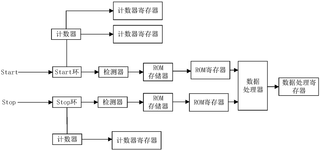
[0066] Such as figure 1 As shown, the present invention provides a time-to-digital conversion circuit based on multiple sampling, including: a counter enable and reset signal generation modu...


PUM


Abstract

The invention provides a time-to-digital conversion circuit based on multiple sampling, including enable reset signal generation module, Start delay loop, Stop delay loop, signal detector, Start delayloop and Stop delay loop counter, counter register, ROM memory, ROM memory register, data processor and data processor register. Start, At the input circuit of the stop signal, Propagate into the Start and Stop delay loops, respectively. The last delay cell of each delay loop is followed by a counter. Output connection register, the enable reset signal generation module is connected to the counter. At the same time, the output of each delay loop is connected with 16 signal detectors to sample the signals for many times. The sampling results are input into ROM memory, and the results of outputconnection register, counter register and ROM memory register are used as input and output connection register of data processor. The technical proposal of the invention solves the problem of low measurement accuracy of the existing time-to-digital converter and realizes higher measurement accuracy.

Description

technical field [0001] The field of the invention is integrated circuit design, and in particular relates to a time-to-digital conversion circuit based on multiple sampling. Background technique [0002] As a basic physical quantity referenced in scientific research experiments and various engineering technologies, time has always attracted much attention. In particular, the measurement of high-precision time intervals is playing an increasingly important role in some fields such as laser ranging, physical experiments, satellite monitoring, and biomedicine. The time-to-digital conversion circuit is a basic means of measuring time intervals. It converts continuous analog time quantities into discrete digital quantities with a certain quantization accuracy, and then realizes the measurement of time intervals and the quantification of time-to-digital converters with different structures. The precision is different, i.e. the resolution is different. [0003] In recent years, t...

Claims


Application Information

Patent Timeline
IPC IPC(8): H03M1/10G04F10/00
CPCG04F10/005H03M1/1071
Inventor 李晶皎柴佳欣金硕巍李贞妮王爱侠闫爱云
Owner NORTHEASTERN UNIV
Learn More