A pretreatment method for desulfurized fly ash of sintering flue gas
A technology for sintering flue gas and desulfurization ash, applied in chemical instruments and methods, magnetic separation, solid separation, etc., can solve the problems of low recovery efficiency of desulfurization ash, pollution of desulfurization ash, etc., to improve the pretreatment effect, promote recovery, improve The effect of friction
- Summary
- Abstract
- Description
- Claims
- Application Information
AI Technical Summary
Problems solved by technology
Method used
Image
Examples
Embodiment 1
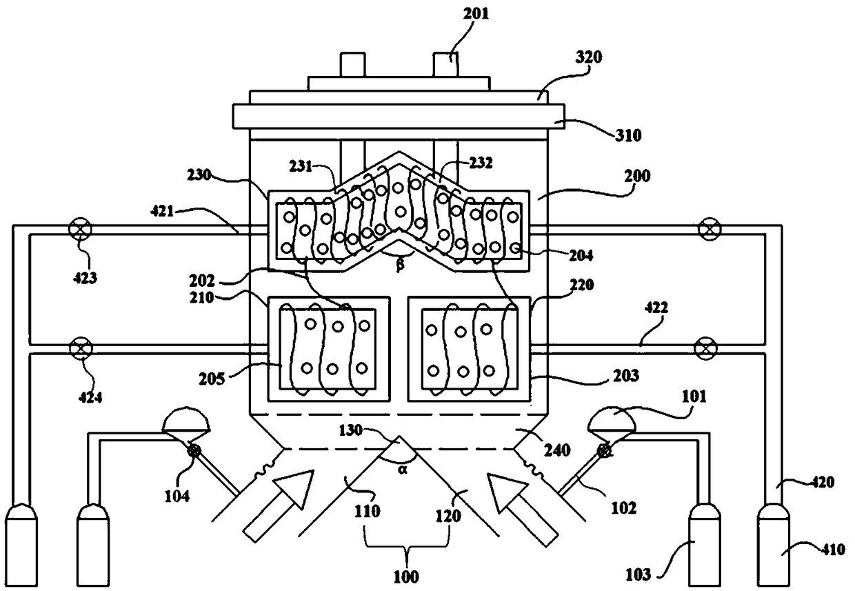
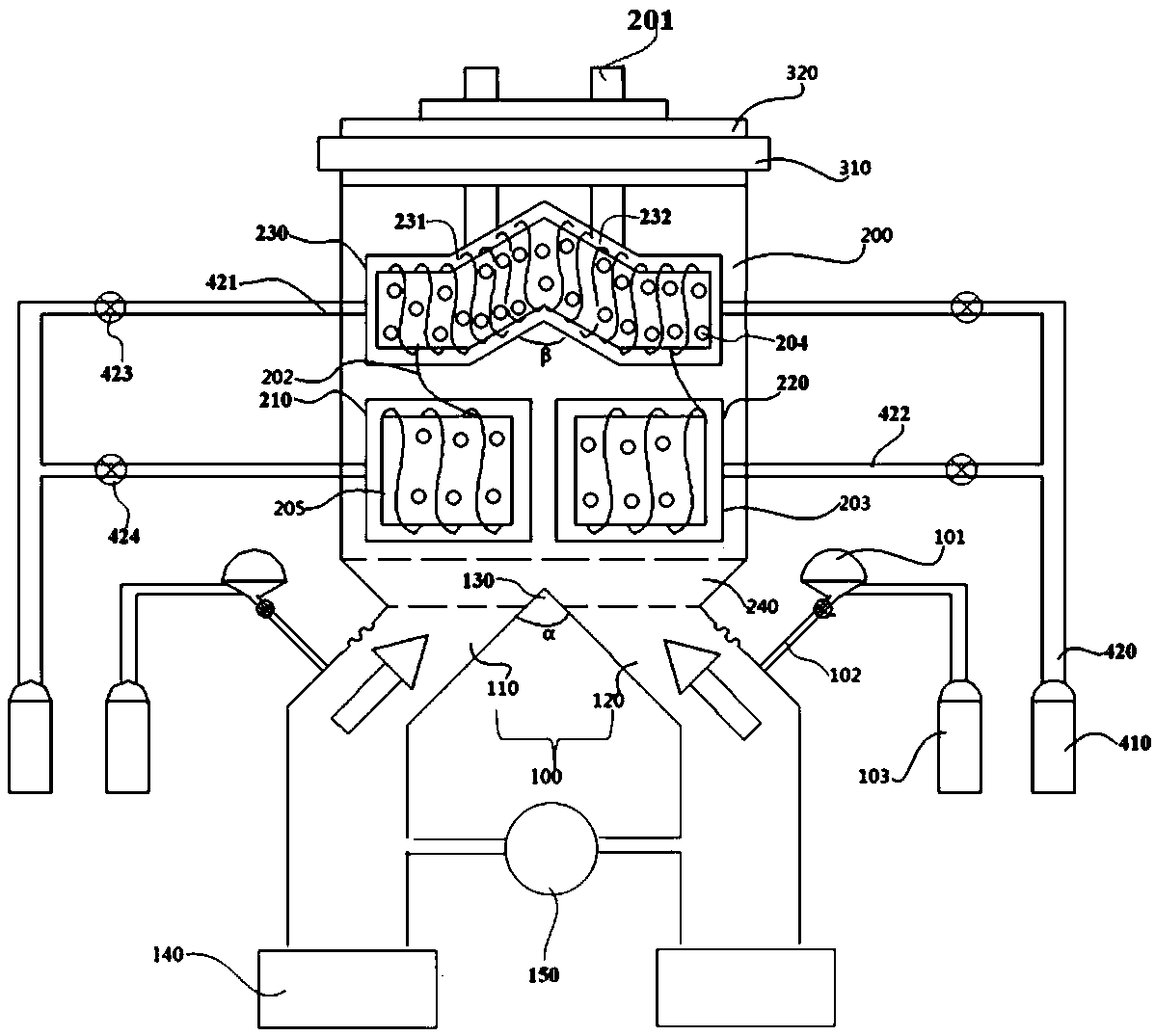
[0044] According to a method for pretreatment of sintering flue gas desulfurization ash in the present invention, the blowing air flow of the air inlet pipe 100 sprays the desulfurization ash into the iron powder recovery cavity 200, and the electromagnet generates magnetic force to adsorb the iron powder in the desulfurization ash to the cotton The surface of the mass sleeve 203, while the blowback airflow of the blowback gas tank 410 overflows outwards through the vent hole 204 on the surface of the electromagnet iron core 205. Such as Figure 5 As shown, the specific steps of the detailed description of the method are as follows:
[0045] Step 1: Turn on the electromagnet and open the air valve of the blowback gas tank 410 at the same time. The blowback air in the blowback gas tank 410 enters the core of the electromagnet iron core 205 through the pipeline, and then the blowback air flows from the surface of the iron core 205 The vent hole 204 of the blowback overflows to ...
Embodiment 2
[0055]The basic content of this embodiment is the same as that of Embodiment 1, and the difference is that: the blowback gas tank 410 is connected with an airflow main pipe 420, and the airflow main pipe 420 is connected with a first airflow branch pipe 421 and a second airflow branch pipe 422, and the first airflow branch pipe 421 communicates with both ends of the iron core 205 of the third electromagnet 230. It is worth noting that: the first air flow branch pipe 421 communicates with the cylinder core of the iron core 205, the cylinder core is a hollow channel, and the surface of the cylinder core and the iron core 205 Vent hole 204 is communicated with each other, and the position that the first air flow branch pipe 421 is connected with cylinder core is provided with seal ring, avoids that blowback airflow leaks from the two ends of iron core 205 cylinder core; It communicates with the iron core 205 of the second electromagnet 220, that is, the second airflow branch pipe ...
Embodiment 3
[0059] The basic content of this embodiment is the same as embodiment 1, as image 3 As shown, the difference is that: the air inlet pipe 100 includes a first air inlet pipe 110 and a second air inlet pipe 120, and the first air inlet pipe 110 and the second air inlet pipe 120 are arranged correspondingly, and the first air inlet pipe 110 The included angle between the first air inlet pipe 110 and the second air inlet pipe 120 is a, and the range of a is 90° to 120°. The blowing air flow makes the desulfurization ash disperse better, and the desulfurization ash is blown from the bottom of the iron powder recovery chamber 200 to the top under the action of the blowing air flow, so as to prevent the desulfurization ash from falling under its own gravity and accumulating in the The iron powder is recycled to the bottom of the cavity 200, thereby promoting full contact between the iron-containing desulfurized ash and the electromagnet, and improving the adsorption efficiency of th...
PUM
 Abstract
Description
Claims
Application Information
 - R&D Engineer
- R&D Manager
- IP Professional
- Industry Leading Data Capabilities
- Powerful AI technology
- Patent DNA Extraction
Browse by: Latest US Patents, China's latest patents, Technical Efficacy Thesaurus, Application Domain, Technology Topic, Popular Technical Reports.
© 2024 PatSnap. All rights reserved.Legal|Privacy policy|Modern Slavery Act Transparency Statement|Sitemap|About US| Contact US: help@patsnap.com


