Inertial control active suspension control system and control method based on vehicle posture deviation

An active suspension and control system technology, which is applied in vehicle suspension/shock absorbing mechanism testing, vehicle springs, elastic suspensions, etc., can solve problems such as complex design process and failure to consider simultaneous design, so as to increase driving speed and reduce vibration Effect

Inactive Publication Date: 2019-01-01
YANSHAN UNIV
View PDF0 Cites 11 Cited by
  • Summary
  • Abstract
  • Description
  • Claims
  • Application Information

AI Technical Summary

Problems solved by technology

When establishing the mathematical model, the attitude control and ride comfort control

Method used


Image

  • Inertial control active suspension control system and control method based on vehicle posture deviation
  • Inertial control active suspension control system and control method based on vehicle posture deviation
  • Inertial control active suspension control system and control method based on vehicle posture deviation

Examples


Embodiment 1

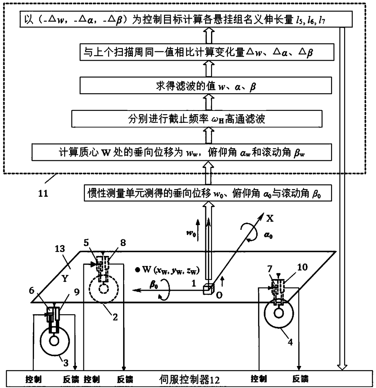
[0039] Embodiment 1: Inertial regulation and active suspension control system of three-wheeled vehicle

[0040] Such as figure 1 As shown, the system includes: car body 13, inertial measurement unit 1, wheels 2, 3, 4 and suspension servo actuating oil cylinders 5, 6, 7 corresponding to the wheels one by one and corresponding displacement sensors 8, 9, 10, electric Control unit 11 and servo controller group 12. The inertial measurement unit 1 is fixed on the car body 13, the wheels 2, 3, and 4 are respectively connected to the lower part of the car body through the suspension servo actuation cylinders 5, 6, and 7, and the displacement sensors 8, 9, and 10 are respectively used to measure the suspension servo action. The strokes of the hydraulic cylinders 5, 6, and 7, the electronic control unit 11 and the servo controller group 12 are fixed on the car body, and the electronic control unit 11 is connected with the inertial measurement unit 1 and the servo controller group 12. T...

Embodiment 2

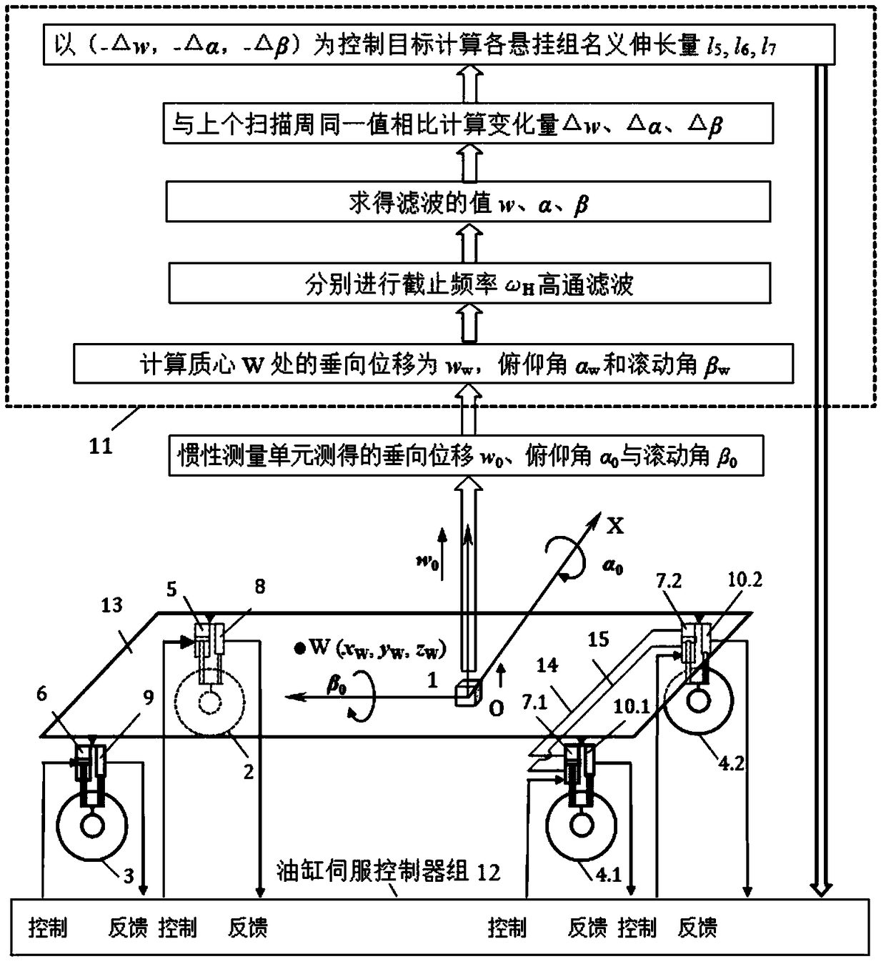
[0051] Embodiment 2: Inertial regulation active suspension control system of four-wheel vehicle

[0052] Such as image 3 As shown, the system includes: car body 13, inertial measurement unit 1, wheels 2, 3, 4.1, 4.2 and suspension servo cylinders 5, 6, 7.1, 7.2 corresponding to the wheels one by one and corresponding displacement sensors 8, 9 , 10.1, 10.2, the electric control unit 11 and the servo controller group 12. The inertial measurement unit 1 is fixed on the car body 13, the wheels 2, 3, 4.1, 4.2 are respectively connected to the bottom of the car body through the suspension servo actuating cylinders 5, 6, 7.1, 7.2, and the displacement sensors 8, 9, 10.1, 10.2 are respectively For measuring the stroke of suspension servo actuating oil cylinders 5, 6, 7.1, 7.2, the electronic control unit 11 and the servo controller group 12 are fixed on the vehicle body, the electronic control unit 11 and the inertial measurement unit 1 and the servo controller group 12 communicati...


PUM


Abstract

The invention discloses an inertial control active suspension control system based on vehicle posture deviation, which comprises a vehicle body, an inertial measurement unit, a plurality of wheels, suspension servo actuating cylinders corresponding to the wheels one by one, and a displacement sensor, an electronic control unit and a servo controller group. When the number of wheels in the group ismore than 1, the upper cavity and the lower cavity of the suspension servo actuating cylinders of the wheels in the group are communicated respectively, so that the wheels in the group become a fulcrum for jointly supporting the vehicle body. Three groups of wheels form three fulcrums, the invention controls the posture of the vehicle body according to the principle that three points determine aplane, according to the changes of vertical displacement, pitch angle and roll angle of the vehicle center of mass, the expansion and contraction of each suspension servo actuator cylinder are controlled, so that the vehicle center of mass moves along a straight line or an arc line and the vehicle posture remains unchanged as far as possible, so that the vibration of the vehicle body is reduced, and the speed, the handling stability and the ride comfort of the vehicle are improved when the vehicle is traveling on the complex road surface.

Description

technical field [0001] The invention belongs to the technical field of vehicle control, and in particular relates to an inertial regulation active suspension control system and a control method based on vehicle pose deviation. Background technique [0002] The suspension system is an important part of the vehicle chassis, and its performance directly determines the ride comfort, operating stability and driving safety of the vehicle. Most traditional vehicles use passive suspension. The suspension parameters are designed according to specific road conditions. Once selected, it is difficult to change and cannot change with road conditions and vehicle speeds. This limits the further improvement of vehicle driving performance. [0003] With the development of electronic information technology and the progress of hydraulic and electric drive technology, the application of controllable suspension in the field of vehicles becomes possible. At present, it is generally believed that...

Claims


Application Information

Patent Timeline
IPC IPC(8): B60G17/018
CPCB60G17/018B60G2500/30B60G2400/252B60G2400/0511B60G2400/0512B60G2401/28B60G2202/40B60G2600/09B60G2800/014B60G2800/012B60G2800/0192B60G2800/0194B60G2300/122B60G17/0165B60G17/0162B60G17/0161B60G17/0152B60G2600/182B62D61/06B60G2400/102B60G2202/413B60G2600/44B60G21/08B60G2600/602B60G17/00B60G17/015G01M17/04B60G2204/62B60G2800/01B60G17/0195
Inventor 赵丁选巩明德刘爽张祝新孙志国倪涛
Owner YANSHAN UNIV
Why Eureka
Try Eureka