Method and apparatus for efficiently purifying silicon material after medium smelting

A medium smelting and purification method technology, applied in chemical instruments and methods, silicon compounds, inorganic chemistry and other directions, can solve the problems of low yield of qualified silicon material, cumbersome production process, high production cost, and achieve increased operational complexity and high efficiency. Smelting, the effect of reducing production efficiency

Active Publication Date: 2019-01-01
QINGDAO BLUE LIGHT NEW MATERIAL CO LTD
View PDF5 Cites 3 Cited by
  • Summary
  • Abstract
  • Description
  • Claims
  • Application Information

AI Technical Summary

Problems solved by technology

[0003] The technical problem to be solved by the present invention is that in the prior art, SiC is generally removed by directional solidification technology, and at the same time, the silicon material after directional solidification is subjected to electron beam or vacuum melting to remove volatile impurities, which leads to cumbersome production process. The process is long, the production cost is too high, and at the same time, the rate of obtaining the final qualified silicon material is low

Method used


Image

  • Method and apparatus for efficiently purifying silicon material after medium smelting
  • Method and apparatus for efficiently purifying silicon material after medium smelting
  • Method and apparatus for efficiently purifying silicon material after medium smelting

Examples


Embodiment 1

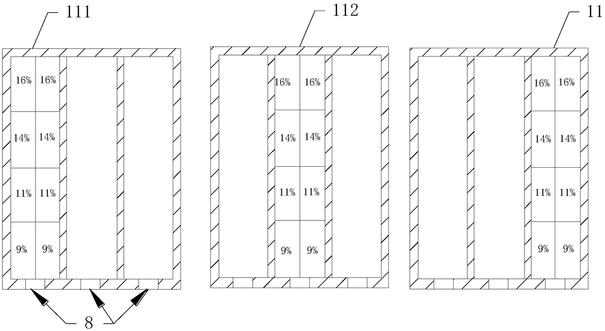
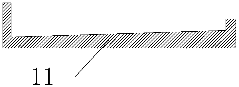
[0040] Such as Figure 2-Figure 3As shown, a device for efficient purification of silicon material after medium smelting, the structure of the melting crucible 11 is inclined from the rear end to the guide liquid port 8; there are several intervals in the melting crucible 11, and each inner groove corresponds to a melting tank. One smelting tank corresponds to one liquid guide port 8 .

[0041] The inclination angle of the melting crucible is 5-10°. Due to the flow of silicon liquid and the downward deposition of silicon carbide, the amount of silicon carbide deposited near the back end of the melting crucible is more, and the closer to the liquid guide port, the smaller the amount of silicon carbide deposited. The melting crucible is designed to be inclined from the rear end to the guide liquid port. , to avoid excessive deposition of silicon carbide at the back end. In the later process of smelting, the melting capacity of the silicon material due to the depth of the molten...

Embodiment 2

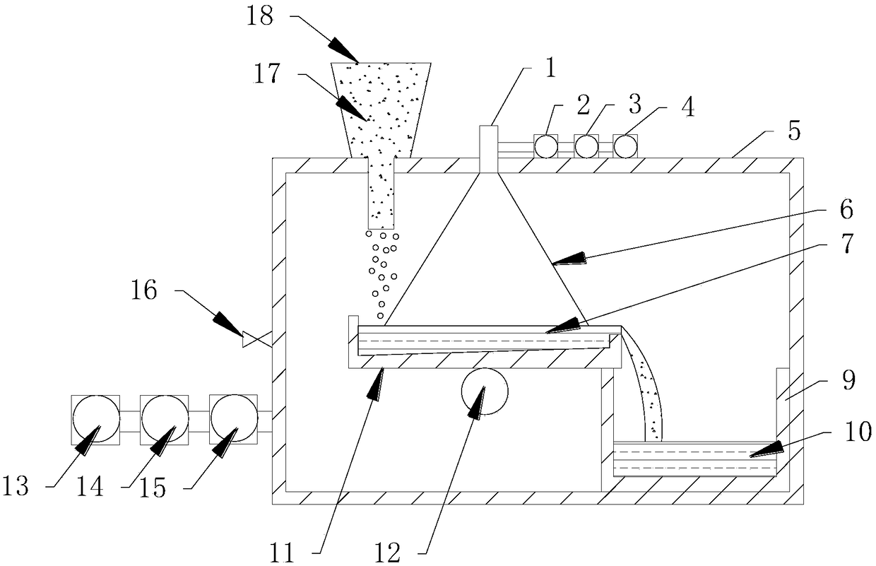
[0062] : The vacuum suction structure on one side of the body of furnace 5 is a mechanical pump I13, a Roots pump I14, and a diffusion pump I15 connected in sequence, and the end of the diffusion pump is connected to the body of furnace to take away the air in the furnace chamber to build a vacuum environment The vacuum suction structure on one side of the electron gun 1 is a molecular pump 2, Roots pump II 3, and mechanical pump II 4 connected in sequence, and the end of the molecular pump is connected with the electron gun 1 to build the vacuum conditions required for electron beam smelting.

[0063] All the other are identical with embodiment 1.

Embodiment 3

[0065] One side of the furnace body 5 is provided with an air charging valve 16 .

[0066] All the other are identical with embodiment 1 or embodiment 2.


PUM

PropertyMeasurementUnit
angleaaaaaaaaaa

Abstract

The invention relates to the field of production of solar-grade polycrystalline silicon, in particular to a method and an apparatus for efficiently purifying a silicon material after the medium smelting. A structure of a smelting crucible of the apparatus is arranged in a manner that the rear end inclines towards a liquid guiding opening; a plurality of compartments are provided in the smelting crucible, an inner groove of each compartment corresponds to one smelting groove, and each smelting groove corresponds to the liquid guide opening; and when in use, the electron beam smelting energy distribution mode corresponding to the structure of the smelting crucible is gradually reduced from the rear end to the liquid guide opening. By selecting the electron beam smelting energy distribution mode and selecting a multi-mode smelting crucible structure, the silicon carbide and volatile impurity element in the silicon material after the medium smelting can be eliminated, the cost is low, andthe effect is good.

Description

technical field [0001] The invention relates to the field of solar-grade polysilicon manufacturing, in particular to a method and device for efficiently purifying silicon material after medium smelting. Background technique [0002] Dielectric smelting is an important process component in the whole production process of preparing solar-grade polysilicon by metallurgical method. It can efficiently remove boron impurities in silicon and obtain silicon material with low boron content. In the process of dielectric smelting, due to the limitation of production process, Carbon and oxygen impurities are introduced, and carbon reacts with liquid silicon to form silicon carbide, which remains in the silicon material after media smelting. At the same time, volatile impurities such as phosphorus contained in the silicon material itself still remain in the silicon material after media smelting. Under the current conditions, SiC is generally removed by directional solidification technolo...

Claims


Application Information

Patent Timeline
Patent Type & Authority Applications(China)
IPC IPC(8): C01B33/037
CPCC01B33/037C01P2006/80Y02P20/10
Inventor 肖承祥庞大宇郭校亮唐子凡侯雨新
Owner QINGDAO BLUE LIGHT NEW MATERIAL CO LTD
Why Eureka
Try Eureka