Fiber collector, oil absorbing material using said collector and manufacturing method of fiber collector

A technology of fiber aggregation and assembly, applied in separation methods, chemical instruments and methods, liquid separation, etc., can solve problems such as complex manufacturing methods, and achieve the effect of strong oil absorption capacity

Pending Publication Date: 2019-01-01
张本 纮邦
View PDF9 Cites 0 Cited by
  • Summary
  • Abstract
  • Description
  • Claims
  • Application Information

AI Technical Summary

Problems solved by technology

[0006] In addition, as shown in Patent Document 2, the long fibers formed by mixing polypropylene fine fibers and polyethylene thick fibers can prevent oil-absorbing materials. The thick fibers are used as bones to solve the problem of compression deformation, but the use of two raw materials with different melting points causes problems. The problem of complex manufacturing methods

Method used


Image

  • Fiber collector, oil absorbing material using said collector and manufacturing method of fiber collector
  • Fiber collector, oil absorbing material using said collector and manufacturing method of fiber collector
  • Fiber collector, oil absorbing material using said collector and manufacturing method of fiber collector

Examples


Embodiment 1

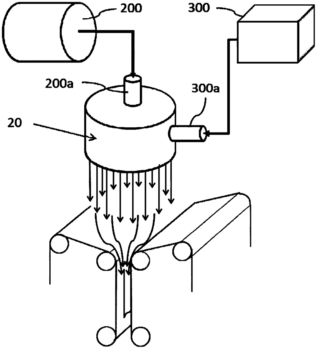
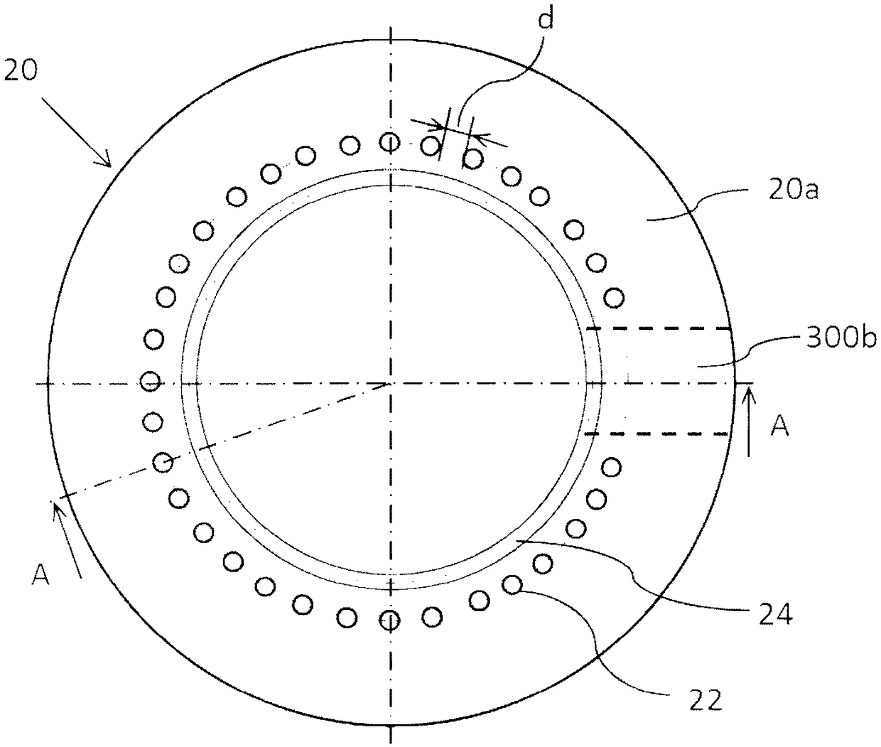
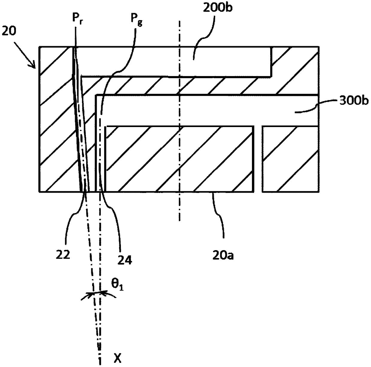
[0070] The extruder for melting polypropylene resin is equipped with figure 2 The nozzle head 20 for melt blowing shown is used, and the nozzle head having the following nozzle conditions is used, and the spinning is performed under the following operating conditions.

[0071]

[0072]

[0073]

[0074]

[0075]

[0076] Here, the temperature of the nozzle is about 300°C. From the beginning of spinning to the end of spinning, basically no temperature change can be observed, and it is almost constant.

[0077] The melted polypropylene resin is spouted from the nozzle for melt blowing, stretched by the high-speed and high-temperature airflow blown from the hot air nozzle, and the fine resin fibers are entangled with each other, twisted into a rope, and then piled up on the conveyor belt. fiber aggregates.

[0078] Figure 4 This is an example of a photograph of a fiber assembly including fiber bundles taken with a low-magnification microscope. The fiber assembly as...

Embodiment 2

[0083] The extruder for melting polypropylene resin is equipped with figure 2 The nozzle head 20 for melt blowing shown is used, and the nozzle head having the following nozzle conditions is used, and the spinning is performed under the following operating conditions. Here, items of head conditions and operating conditions that are the same as in Example 1 are omitted.

[0084] Assembled on the extruder figure 2 The nozzle 20 for melt-blowing is shown, and the nozzle having the following nozzle conditions is used, and the melted polypropylene resin is spun under the following operating conditions. Here, the items of head conditions and operating conditions that are the same as those in Embodiment 1 are omitted.

[0085]

[0086] Liquid nozzle hole φ0.35mm×78

[0087] Liquid nozzle interval 1.15mm

[0088]

[0089] Resin output 5~13kg / hr

[0090] Hot air (air) temperature 330°C

[0091] The temperature of the nozzle here is 330° C. From the beginning of spinning to ...


PUM

PropertyMeasurementUnit
diameteraaaaaaaaaa
diameteraaaaaaaaaa
diameteraaaaaaaaaa

Abstract

The invention provides a fiber collector formed by ultra-thin fibers of micro-fibers and which is bulky and high in shape retention, an oil absorbing material using said fiber collector which is highin oil absorbing performance and not easy to collapse and a manufacturing method of the fiber collector. The diameter of the ultra-fine fiber forming the fiber collector is 0.2 to 4 [mu]m. The fiber collector is characterized in that at least a portion of the ultra-fine fibers are assembled in bundles in the longitudinal direction, and at least a portion of the bonded fiber bundles have a diameterof more than 5 [mu]m.

Description

technical field [0001] The present invention relates to a fiber assembly which is used as an oil-absorbing material and a method for producing the fiber assembly. Background technique [0002] It is known to use fibers of various materials and diameters as oil adsorbents in order to recover oil that has flowed onto sea and water surfaces. For example, Patent Document 1 proposes to use a nanofiber laminate of a polypropylene material whose fibers are directly 100 to 500 nm in size as an oil-absorbing material. In patent document 2, it is proposed to use long-fiber non-woven fabric composed of thin fibers of polypropylene and thick fibers of polyethylene as an oil-absorbing material. [0003] [Patent Document 1] JP-A-2013-184095 [0004] [Patent Document 2] JP-A-2014-240537 [0005] However, the laminate of micronanofibers with a fiber diameter of 100 to 500 nm shown in Patent Document 1 is used as an oil-absorbing material, and the fiber strength is very weak, and a slight...

Claims


Application Information

Patent Timeline
Patent Type & Authority Applications(China)
IPC IPC(8): D02G3/02D01D5/08D01D5/12B01D17/022E02B15/04E02B15/10
CPCB01D17/0202D01D5/08D01D5/14D02G3/02E02B15/045E02B15/101Y02A20/204
Inventor 张本纮邦
Owner 张本 纮邦
Why Eureka
Try Eureka