
Digital beam forming method for multi-carrier broadband signal

A wideband signal, digital beam technology, applied in the field of array signal processing, can solve the problems such as inability to use digital beam, low probability of interception, multi-mode time resource shortage, etc.

Active Publication Date: 2019-01-01
HOHAI UNIV
View PDF7 Cites 18 Cited by
  • Summary
  • Abstract
  • Description
  • Claims
  • Application Information

AI Technical Summary

Problems solved by technology

[0003] In recent years, the multi-carrier phase coding (MCPC) signal or orthogonal frequency division multiplexing (OFDM) signal, which has been widely studied by the radar community in the world, has the characteristics of both narrowband signal and wideband signal, and has high spectrum efficiency, frequency diversity, and time Diversity, wideband measurement, low probability of interception, short-time Doppler frequency measurement, etc. The radar adopts multi-carrier signals and can work in multiple modes at the same time based on frequency division multiplexing, which solves the shortage of time resources in multi-modes of multi-target search, tracking, imaging, and guidance However, the multi-carrier signal has a large peak-to-average envelope power ratio (PMEPR), so it cannot use high-efficiency saturated power amplifiers, nor can it use traditional digital beamforming technology , therefore, digital beamforming of multi-carrier signals becomes a bottleneck technology for radars using multi-carrier signals

Method used


Image

  • Digital beam forming method for multi-carrier broadband signal
  • Digital beam forming method for multi-carrier broadband signal
  • Digital beam forming method for multi-carrier broadband signal

Examples


Embodiment Construction

[0060] Embodiments of the present invention are described in detail below, examples of which are shown in the drawings, wherein the same or similar reference numerals denote the same or similar elements or elements having the same or similar functions throughout. The embodiments described below by referring to the figures are exemplary only for explaining the present invention and should not be construed as limiting the present invention.

[0061] Those skilled in the art can understand that, unless otherwise defined, all terms (including technical terms and scientific terms) used herein have the same meaning as commonly understood by one of ordinary skill in the art to which this invention belongs. It should also be understood that terms such as those defined in commonly used dictionaries should be understood to have a meaning consistent with the meaning in the context of the prior art, and will not be interpreted in an idealized or overly formal sense unless defined as herein...


PUM


Abstract

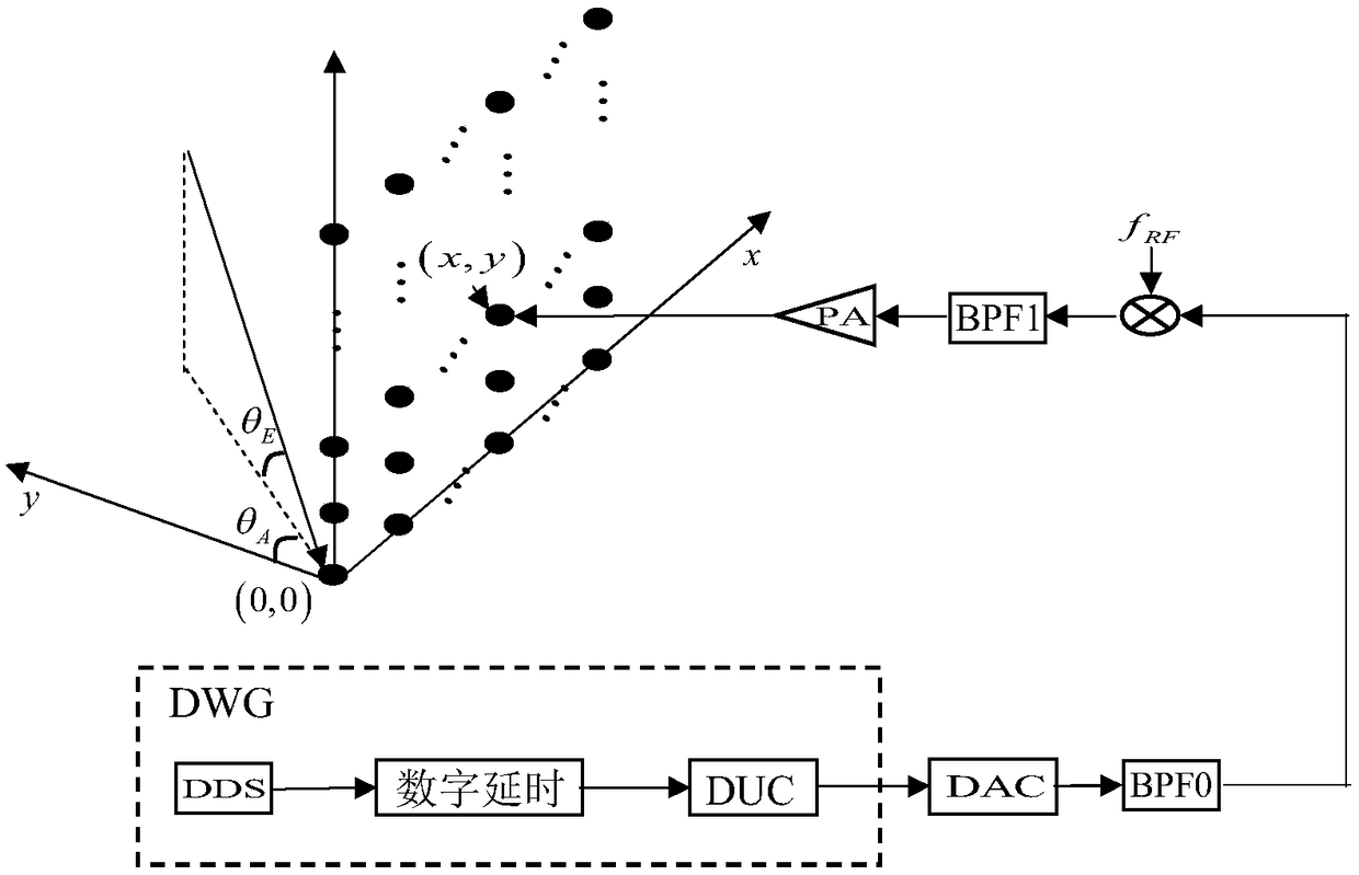
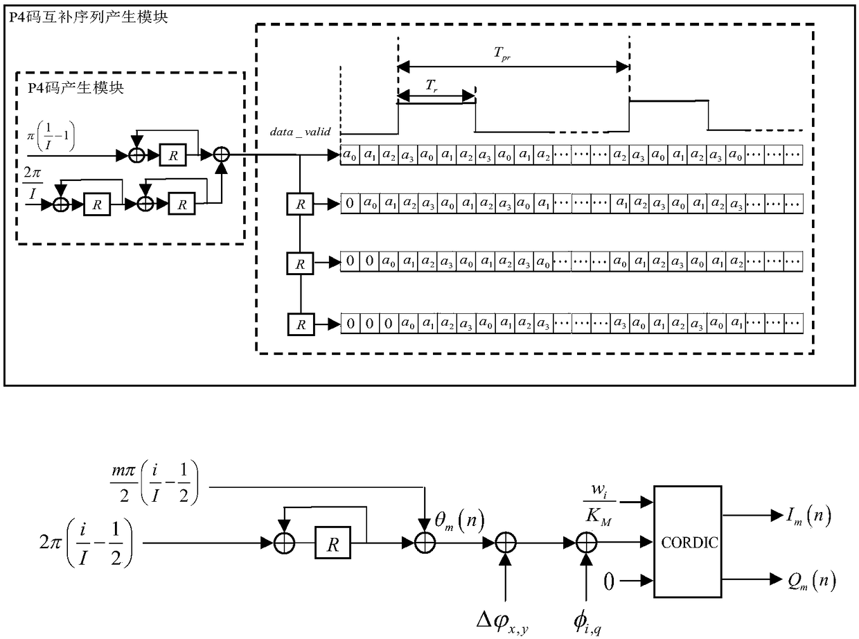
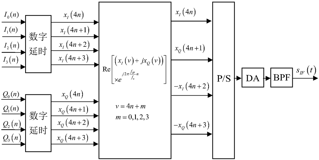
The invention discloses a digital beam forming method for a multi-carrier broadband signal. On the basis of a multi-phase processing technology, a sub-carrier DDS is designed in an FPGA; double accumulators and a register generate a P4 complementary code encoding phase in a delay manner; a compensation phase and a time delay are calculated according to a serial number of a sub carrier radio-frequency signal transmitting antenna unit; a phase code and a sub carrier baseband signal after phase compensation are generated based on a CORDIC algorithm by using the accumulator; digital delay, digitalup-conversion, digital-to-analog conversion, and intermediate-frequency filtering are carried out to output an analog subcarrier intermediate-frequency signal; a frequency-agility local-oscillator signal is generated by using an externally inputted reference clock signal, mixing and filtering are carried out on all sub carrier intermediate-frequency signals and the frequency-agility local-oscillator signal to generate sub carrier radio-frequency signals, power amplification is carried out and the processed signals are transmitted by antenna units; and the sub carrier radio-frequency signals transmitted by all antenna units are synthesized into a multi-carrier broadband signal in space. According to the invention, with phase control and continuously variable digital delay control, digitalbeam forming of the multi-carrier signal is realized.

Description

technical field [0001] The invention relates to a digital beamforming method for multi-carrier broadband signals, in particular to a digital beamforming method for multi-carrier signals based on continuously variable digital delay and phase compensation, and belongs to the technical field of array signal processing. Background technique [0002] Existing phased array radars use single-carrier-modulated waveforms (such as frequency modulation or phase-coded signals) for search, tracking, imaging, and other modes. Different modes use waveforms with different resolutions; they are subject to platform space, stealth, payload, electromagnetic compatibility, etc. Restricted by factors, several modes of phased array radar multi-target guidance and target detection often use the same array antenna, multiple modes use antennas in time-sharing, and radar time resources are dynamically allocated among several modes according to time slots. In the case of search and multi-target trackin...

Claims


Application Information

Patent Timeline
Patent Type & Authority Applications(China)
IPC IPC(8): G01S7/02
CPCG01S7/02
Inventor 蒋德富钱荣李建峰付伟蒋康辉韩燕王峰麻清华
Owner HOHAI UNIV
Learn More