
Cutting path planning method applied to folded waveguide slow wave structure

A slow-wave structure, folded waveguide technology, applied in automatic control devices, feeding devices, milling machine equipment, etc., can solve the problems of easy inclination of side walls of deep grooves, easy bending and collapse of island structures, and difficult removal of burrs.

Active Publication Date: 2019-01-04
HARBIN INST OF TECH
View PDF5 Cites 10 Cited by
  • Summary
  • Abstract
  • Description
  • Claims
  • Application Information

AI Technical Summary

Problems solved by technology

[0004] The purpose of the present invention is to provide a method for planning the tool trajectory applied to the folded waveguide slow-wave structure, so as to solve the problem that the island structure is prone to bending and collapse during the ultra-precision micro-milling process of such parts, and the straight groove and S-shaped groove The burr formed at the junction is not easy to remove, and the side wall of the deep groove is easy to tilt, etc.

Method used

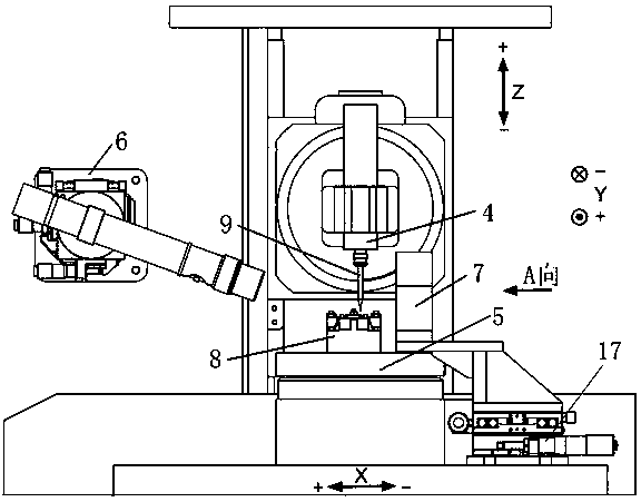
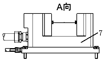

Image

  • Cutting path planning method applied to folded waveguide slow wave structure
  • Cutting path planning method applied to folded waveguide slow wave structure
  • Cutting path planning method applied to folded waveguide slow wave structure

Examples


Embodiment Construction

[0057] Below in conjunction with accompanying drawing and embodiment the present invention is described in further detail:

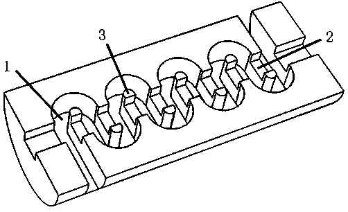
[0058] The invention relates to a method for planning the trajectory of a knife applied to a folded waveguide slow wave structure, which is used for processing such as figure 1 The folded waveguide slow-wave structure shown. The slow wave structure is a semi-cylindrical body cut in the axial direction, and S-shaped grooves 1, straight grooves 2, and islands 3 formed by the intersection of the two are distributed on the axial section. The S-shaped grooves have a total of 75 periods, and the S-shaped grooves The aspect ratio is 255μm / 100μm, and the straight groove channel width is 140μm. The material of the slow wave structure is Al 2 o 3 For dispersed oxygen-free copper with a particle volume fraction of 1.1% and a particle size of 50-100nm, it is required that the dimensional accuracy after processing should be better than ±2μm, and the surface roughn...


PUM


Abstract

The invention relates to a cutting path planning method applied to a folded waveguide slow wave structure. The cutting path planning method comprises the following steps: removing oxide scales on thesurface of a material by adopting a milling cutter; selecting a point, positioned outside the starting edge of an S-shaped groove, on a center line of a straight groove as a cutter adjusting point; performing Z-direction cutter adjustment on a workpiece by adopting a CCD cutter adjusting system; dividing the processing stage, planning a cutting path of a micro-milling cutter and adopting a cuttingplan for layered processing of the slow wave structure in the depth direction; finally removing residual burrs through an auxiliary process. The cutting path planning method provided by the inventionhas the benefits that the ultra-precision micro-milling process of the multi-period, large-aspect ratio and thin-walled complex slow-wave structure is realized, and the problems that in the ultra-precision micro-milling process of the part, an island structure is prone to bending and collapsing, the burrs formed at the intersection of the straight groove and the S-shaped groove are hard to remove, the side wall of a deep groove is easy to incline and the like are solved, to meet the relatively stringent processing requirements.

Description

technical field [0001] The invention belongs to the field of ultra-precise micro-milling processing, and relates to a method for planning a knife trajectory applied to a folded waveguide slow-wave structure, in particular to a planning method for a knife trajectory during micro-milling of a folded waveguide slow-wave structure with a working frequency of 0.34THz method. Background technique [0002] In view of the characteristics of terahertz waves such as strong penetration, high use safety, high orientation and high bandwidth, terahertz technology has become an extremely important cutting-edge technology in the world. In national defense and military affairs, broadband radar designed with terahertz technology can realize sensitive detection and precise positioning of tiny targets; in the field of information technology, terahertz technology can provide strong guarantee for military communication encryption and space communication. In addition, terahertz technology can als...

Claims


Application Information

Patent Timeline
Patent Type & Authority Applications(China)
IPC IPC(8): B23C3/00B23Q15/013B23Q15/007
CPCB23C3/00B23Q15/007B23Q15/013
Inventor 吴春亚陈明君韩鹏宇王廷章鲁义凡段从繁
Owner HARBIN INST OF TECH
Learn More