Dry anaerobic system for treating high-concentration organic wastes

An organic waste and dry anaerobic technology, which is applied in the field of high-concentration organic waste treatment, disposal, and resource utilization, can solve the problems of incomplete resource utilization of discharged biogas slurry, large reactor sediments and scum, and volumetric production. Low gas rate and other problems, to achieve the effect of fewer types of applicable materials, expanding economic benefits, and low volumetric gas production rate

Pending Publication Date: 2019-01-04
湖北农谷能源建设有限公司 +1
View PDF9 Cites 1 Cited by
  • Summary
  • Abstract
  • Description
  • Claims
  • Application Information

AI Technical Summary

Problems solved by technology

[0006] 1) The system effectively solves the problem that the traditional wet anaerobic system cannot fully utilize the biogas slurry;
[0008] 3) The system solves the problems of wet fermentation: ①Large amount of biogas slurry; ②Complicated pretreatment and large process volume; ③There are many sediments and scum in the reactor, and the cleaning cycle is short; ④Low volume load and low volume gas production rate

Method used


Image

  • Dry anaerobic system for treating high-concentration organic wastes
  • Dry anaerobic system for treating high-concentration organic wastes

Examples


Embodiment 1

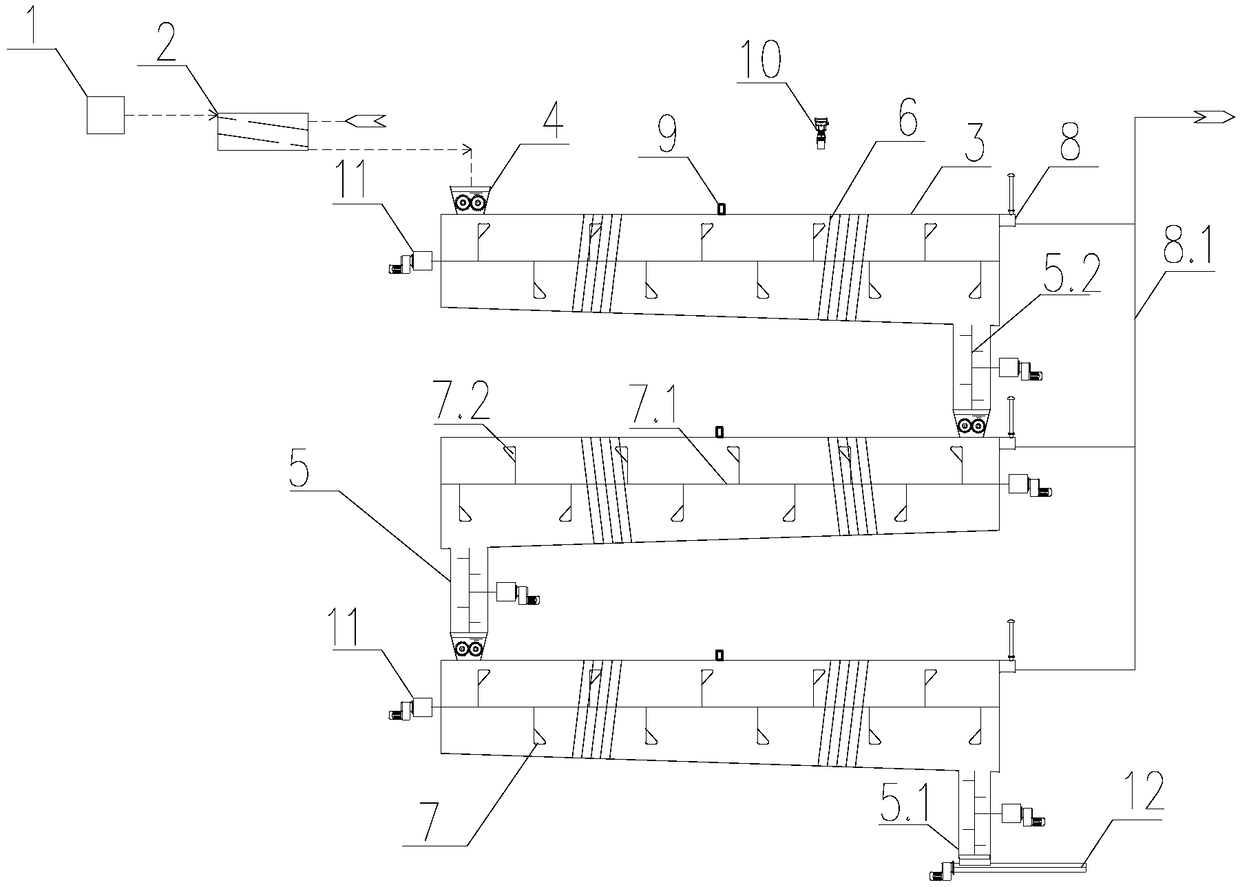
[0034] Such as figure 1 The series-type high-concentration organic waste dry-type anaerobic system shown includes anaerobic feeder 1 and anaerobic inoculator 2 in turn, anaerobic inoculator 2 and three dry anaerobic reactors in series. Connect, the dry anaerobic reactor comprises anaerobic fermentation chamber 3, and the section of anaerobic fermentation chamber 3 is rectangular trapezoidal,

[0035] The anaerobic fermentation chamber 3 provides a physical and chemical environment for mesophilic or high-temperature anaerobic microorganisms, and the reaction chamber is closely connected with multiple auxiliary devices and works together. The operating pressure of the reaction chamber is 0-3500Pa, the residence time is 10-30d, and the volumetric gas production rate is 1-4m 3 / m 3 d. The temperature of medium-temperature fermentation is 35-38°C, and the temperature of high-temperature fermentation is 50-55°C. The reaction chamber is a horizontal steel structure, and the bottom...

Embodiment 2

[0042] Such as figure 2 The parallel high-concentration organic waste dry anaerobic system shown is basically the same as the structure, the difference is:

[0043] The connection between the anaerobic inoculator 2 and three parallel dry anaerobic reactors; the bottom of the discharge pipe 5.1 of each dry anaerobic reactor is provided with a discharge conveyor 12 .

[0044] According to the actual situation, the pretreated material enters the anaerobic fermentation chamber 3 of different dry anaerobic reactors through the anaerobic feed funnel 4 after being inoculated by the anaerobic inoculator 2 .


PUM


Abstract

The invention discloses a dry anaerobic system for treating high-concentration organic wastes. The dry anaerobic system sequentially comprises an anaerobic feeder and an anaerobic inoculator, whereinthe anaerobic inoculator is connected with a plurality of dry anaerobic reactors in parallel or is serially connected with a plurality of dry anaerobic reactors end to end; each dry anaerobic reactorcomprises an anaerobic fermentation chamber; anaerobic feeding hoppers are arranged on the upper parts of the anaerobic fermentation chambers; the other ends of the anaerobic feeding hoppers are sequentially connected with the anaerobic inoculator through pipes; anaerobic discharging devices are arranged on the lower parts of the anaerobic fermentation chambers; the inner walls of the anaerobic fermentation chambers are wound with heating and heat-insulating devices; horizontal plow-shaped stirrers hinged to the two ends of the anaerobic fermentation chambers are arranged inside the anaerobicfermentation chambers; biogas collecting devices are mounted on the outer walls of the other ends of the anaerobic fermentation chambers; each biogas collecting device is connected with a connecting pipe. In a process technology from pollution to recycling, the efficiency of converting organic matters into inorganic matters is improved, the yield of biomass gas is increased, economic benefits areincreased, and the difficulty of difficult elimination in the process of returning a biogas slurry to a field is overcome.

Description

technical field [0001] The invention relates to the technical field of high-concentration organic waste treatment, disposal, source utilization, and in particular to a dry anaerobic system for high-concentration organic waste. Background technique [0002] Anaerobic fermentation technology is the optimal technical route choice for treating high-concentration organic waste pollutants. It has the advantages of high degradation efficiency, low energy consumption, low equipment investment, and many by-products. It has been widely used in agriculture, forestry, animal husbandry and environmental protection industries. After a hundred years of development, anaerobic reactors are also constantly updated according to environmental needs. Under the requirements of current environmental protection policies, resource utilization is more important than harmlessness and reduction. Important, so in order to realize the dream of zero emissions, continuous innovation and breakthroughs in te...

Claims


Application Information

Patent Timeline
Patent Type & Authority Applications(China)
IPC IPC(8): C12M1/107C12M1/16C12M1/34C12M1/02C12M1/00
CPCC12M21/04C12M21/16C12M23/58C12M27/06C12M41/34
Inventor 周洋罗炬
Owner 湖北农谷能源建设有限公司
Why Eureka
Try Eureka