
Vacuum heat treatment furnace with chemical oxygen-removing system

A vacuum heat treatment furnace and chemical deoxidization technology, applied in heat treatment furnaces, heat treatment equipment, furnaces, etc., can solve the problems of long heating time, low heating speed, low radiation efficiency, etc., to reduce power consumption and mechanical wear, reduce heating The effect of time and heating rate is fast

Pending Publication Date: 2019-01-04
SHANGHAI YIBAI IND FURNACES CO LTD
View PDF0 Cites 1 Cited by
  • Summary
  • Abstract
  • Description
  • Claims
  • Application Information

AI Technical Summary

Problems solved by technology

[0005] Because the heat transfer method of vacuum heating is single radiation heat transfer, the radiation efficiency is low in the heating stage, especially in the back radiation and hidden places, which rely on indirect radiation and conduction heat to heat up, so the heating rate is low and the heating time is long. The temperature difference between the working surface and the furnace indication is large
The vacuum environment requires the vacuum pump to run continuously, so the long-term heating process increases the power consumption and mechanical wear of the vacuum pump

Method used


Image

  • Vacuum heat treatment furnace with chemical oxygen-removing system
  • Vacuum heat treatment furnace with chemical oxygen-removing system

Examples


Embodiment

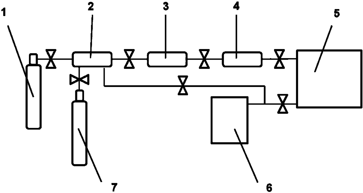
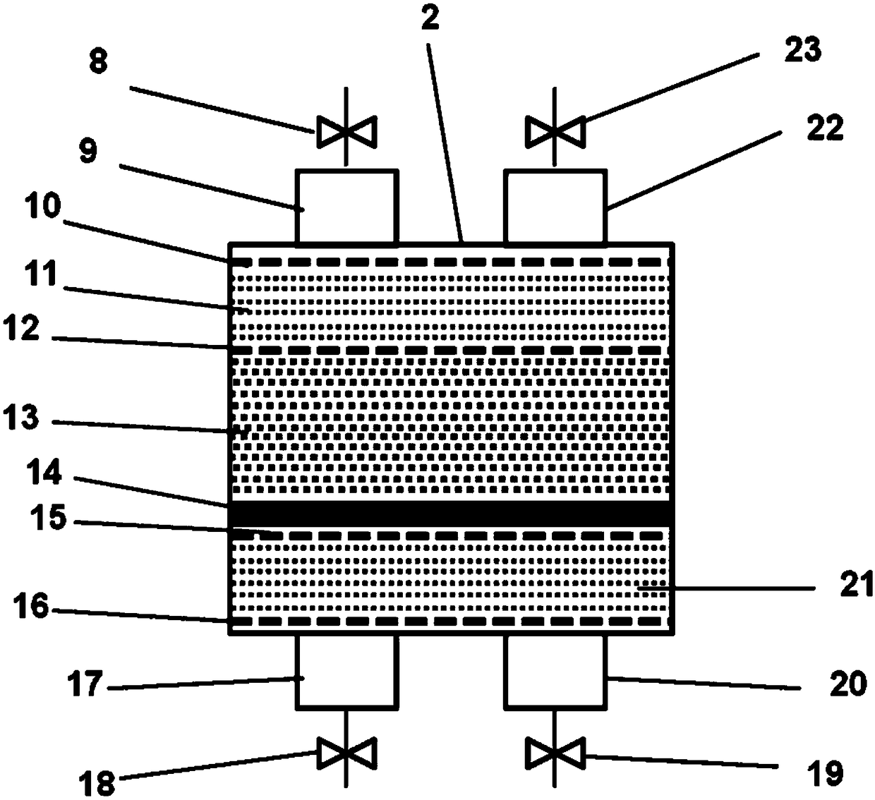
[0027] like Figure 1~2 As shown, a vacuum heat treatment furnace with a chemical deoxidation system includes a shielding gas cylinder 1, a vacuum furnace chamber 5 and a vacuum pump 6, the shielding gas cylinder 1 and the vacuum pump 6 are respectively connected to the vacuum furnace chamber 5, and the vacuum heat treatment furnace also includes Deoxygenation tank 2, one end of the deoxygenation tank 2 is connected to the protective gas source 1 through the protective gas inlet valve 18, and the other end is connected to the vacuum furnace chamber 5 through the protective gas outlet valve 23, and the deoxygenation tank 2 is equipped with a deoxygenation layer 13 and heater 14.

[0028] The vacuum heat treatment furnace also includes a reducing gas source 7, which is connected to one end of the oxygen removal tank 2 through a reducing gas inlet valve 19, and the other end of the oxygen removal tank 2 is connected to a vacuum pump 6 through a reducing gas outlet valve 8.

[00...


PUM


Abstract

The invention relates to a vacuum heat treatment furnace with a chemical oxygen-removing system. The vacuum heat treatment furnace with the chemical oxygen-removing system comprises a protective gas source (1), a vacuum furnace chamber (5) and a vacuum pump (6), wherein the protective gas source (1) and the vacuum pump (6) are connected with the vacuum furnace chamber (5) respectively; the vacuumheat treatment furnace further comprises an oxygen-removing tank (2); one end of the oxygen-removing tank (2) is connected with the protective gas source (1) through a protective gas inlet valve (18),and the other end of the oxygen-removing tank (2) is connected with the vacuum furnace chamber (5) through a protective gas outlet valve (23); an oxygen-removing layer (13) and a heater (14) are arranged in the oxygen-removing tank (2). Compared with the prior art, the vacuum heat treatment furnace with the chemical oxygen-removing system has the following advantages: the oxygen-removing tank isarranged behind the protective gas source, so that a vacuum furnace works in the pressure range of 10<2> Pa, an oxygen-free environment is created for a workpiece, the fact that the workpiece is not oxidized during heating is guaranteed, the temperature increasing speed of the vacuum furnace is high, the temperature increasing time is shortened, the vacuum furnace does not need to be provided witha turbo molecular pump, and power consumption and mechanical wear caused by the vacuum pump are greatly reduced.

Description

technical field [0001] The invention relates to a vacuum heat treatment furnace, in particular to a vacuum heat treatment furnace with a chemical oxygen removal system. Background technique [0002] Vacuum heat treatment refers to the heat treatment process of parts using a vacuum furnace. The heating method of the vacuum furnace in a vacuum state is radiation, the heating speed is slow, the degree of automation is high, the temperature uniformity is good, the process reproducibility is good, and the processed parts have deformation It is characterized by small size, good surface condition, and high service life. It is widely used in the field of small parts and key parts. Especially for parts with very strict deformation requirements, vacuum furnaces can solve this heat treatment problem. [0003] The development of vacuum heat treatment is inseparable from heat treatment equipment. From the original oil quenching furnace, gas quenching oil cooling furnace to gas quenching...

Claims


Application Information

Patent Timeline
IPC IPC(8): C21D1/773C21D9/00
CPCC21D1/773C21D9/00
Inventor 杨景峰郁伟荣沈鹏
Owner SHANGHAI YIBAI IND FURNACES CO LTD
Learn More