Low-voltage low-power ultrasonic atomizer driving circuit and driving method thereof
What is AI technical title?
AI technical title is built by Patsnap AI team. It summarizes the technical point description of the patent document.
A driving circuit and atomization circuit technology, applied in logic circuits, logic circuit coupling/interfaces using field effect transistors, logic circuit interface devices, etc., can solve problems such as difficult to clean, easy to foam, and block the mist outlet
Inactive Publication Date: 2019-01-04
广州厚达电子科技有限公司
View PDF6 Cites 3 Cited by
Summary
Abstract
Description
Claims
Application Information
AI Technical Summary
This helps you quickly interpret patents by identifying the three key elements:
Problems solved by technology
Method used
Benefits of technology
Problems solved by technology
[0003] The 5V ultrasonic nebulizer that is popular now is used to boost the voltage and then supply power to the atomization circuit. The energy cover is basically useless, and the use of the energy-concentrating cover will bring many adverse consequences, such as difficult to clean, easy to foam and block the fog hole without fogging. Provide a low-cost energy-saving cover that does not need to be installed , low voltage and low power consumption, compared with the current popular circuit, at the same input voltage, the same input current, the same atomization sheet, the same atomization structure, the amount of fog produced by the ultrasonic atomizer of this technical solution It is more than 1 times larger than the traditional fog volume, and the depth of the atomized water level is more than 1.3 times that of the traditional one. The ultrasonic atomizer that can increase the atomization volume is an urgent demand in the market today, and has market potential.
Method used
Image
Click on the blue label to locate the original text in one second.
Reading with bidirectional positioning of images and text.
Examples
Embodiment 1
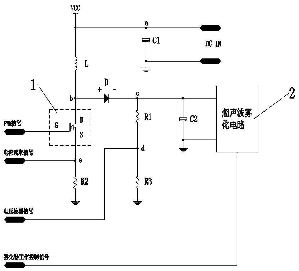
[0051] Embodiment 1, refer to attached figure 1 And attached image 3 shown, including the following steps:
[0052] Step 1. Provide a low-voltage and low-power ultrasonic nebulizer drive circuit, including a MOS tube 1, an inductor L, a diode D, a resistor, a capacitor, and an ultrasonic nebulizer circuit 2;
[0053] When the circuit structure of MOS tube 1 is selected, the PWM signal is connected to the G pole end of the MOS tube 1, the current reading signal is connected to the S pole end, the voltage detection signal is connected to the fourth node d, and the ultrasonic atomization circuit is connected. Input the working control signal of the nebulizer.
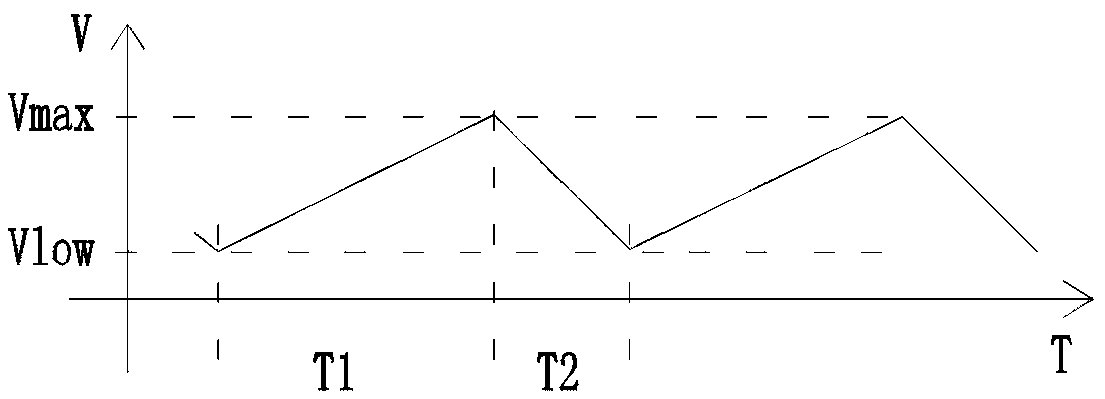
[0054] Step 2: In the initial charging stage, the MOS tube 1, the inductor L and the diode D charge the capacitor C2, the charging time T1 of the capacitor C2 is 1ms~300ms, the maximum voltage Vmax of the capacitor C2 is 7V~35V, and the fourth Node d is connected to a voltage detection signal for voltage detection.
...
Embodiment 2
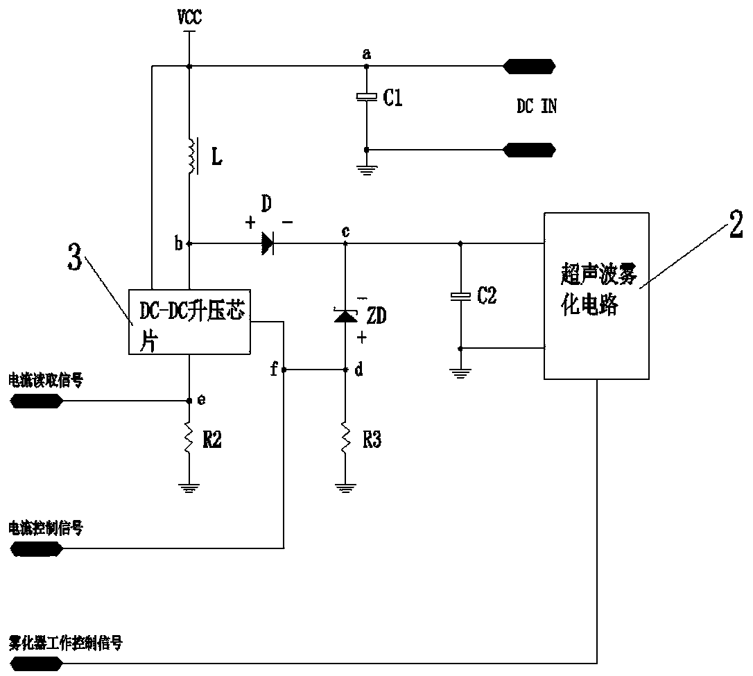
[0059] Embodiment 2, refer to attached figure 2 And attached image 3 shown, including the following steps:
[0060] Step 1. Provide a low-voltage and low-power ultrasonic nebulizer driving circuit, including a DC-DC boost chip, an inductor L, a diode D, a Zener diode ZD, a resistor, a capacitor, and an ultrasonic nebulizer circuit 2;
[0061] When the DC-DC boost chip 3 circuit structure is selected, the current reading signal is connected to the fifth node e, the current control signal is connected to the sixth node f, and the nebulizer working control signal is connected to the ultrasonic atomization circuit .
[0062] Step 2, in the initial charging stage, the DC-DC boost chip 3 boosts the capacitor C2, the charging time T1 of the capacitor C2 is 1ms~300ms, the maximum voltage Vmax of the capacitor C2 charging is 7V~35V, the sixth node f Access the current control signal for voltage control.
[0063] Step 3. Ultrasonic nebulizer atomization working stage:
[0064] Co...
PUM
Abstract
The invention discloses a low-voltage low-power ultrasonic atomizerdriving circuit and a driving method thereof, which are applied to an ultrasonic atomizer. The low-voltage low-power ultrasonic atomizerdriving circuit comprises a MOS tube, an inductor L, a diode D, a resistor, a capacitor and an ultrasonic atomizing circuit, wherein the working current of a DC 2.7 V to 6V power supply is 300MAto 1.5 A. The MOS tube or a DC- DC boost chip circuit structure performs a period of time of charging, boosting and atomization on the capacitor, so that the capacitor accumulates a larger amount of energy. The MOS transistordriving circuit receives a PWM signal and a circuit reading signal to control the stability of input current, and receives a voltage detection signal to control the atomization working time of ultrasonic atomizer. T The DC-DC boost chipdriver circuit receives a current reading signal and a current control signal to control the stability of input current. The ultrasonic atomizing circuit is connected with atomizer control signal to control starting and stopping of atomization. Therefore the ultrasonic atomize has good mist quantity and water depth adaptability, thereby realizing no requirement for arrangement of an energy gathering cover and realizing working effects of repeated charging and repeated atomization.
Description
technical field [0001] The invention relates to the technical field of ultrasonic nebulizers, in particular to a driving circuit and a driving method of an ultrasonic nebulizer with low voltage and low power consumption. Background technique [0002] Ultrasonic atomization devices used for humidification, fragrance, sterilization or decoration in daily life can atomize the liquid contained in the liquid container through the ultrasonic wave generated by the ultrasonic generator, so as to realize its atomization function. Traditional ultrasonic The atomizer is composed of a transducer and a drive circuit. Its operating frequency is generally 1.7MHZ, 2MHZ, 2.4MHZ, 3MHZ, 3.3MHZ and 3.5MHZ, etc. The power generally needs to be greater than 4 watts to generate enough energy to atomize water. And meet the needs of practical use. For low-voltage use, such as equal to 5V, the energy required to produce a practical atomization effect will be greater, and the energy required is great...
Claims
Application Information
Patent Timeline
Application Date:The date an application was filed.
Publication Date:The date a patent or application was officially published.
First Publication Date:The earliest publication date of a patent with the same application number.
Issue Date:Publication date of the patent grant document.
PCT Entry Date:The Entry date of PCT National Phase.
Estimated Expiry Date:The statutory expiry date of a patent right according to the Patent Law, and it is the longest term of protection that the patent right can achieve without the termination of the patent right due to other reasons(Term extension factor has been taken into account ).
Invalid Date:Actual expiry date is based on effective date or publication date of legal transaction data of invalid patent.

