Ceramic packing air drying room

A technology of ceramic packing and drying room, which is applied in the direction of dryer, drying, and drying machine for static materials, which can solve the problems of long time, high energy consumption, air drying efficiency, and uneven air outlet.

Inactive Publication Date: 2019-01-08
李亿明
View PDF10 Cites 2 Cited by
  • Summary
  • Abstract
  • Description
  • Claims
  • Application Information

AI Technical Summary

Problems solved by technology

[0003] In the production process of ceramic corrugated filler, the most critical process is to place the ceramic filler mud in the kiln for high-temperature sintering. Before the filler is placed in the kiln, there is another step to remove water and dry, because the ceramic filler After being extruded, it is moist and contains a lot of water. If it is directly placed in the kiln for sintering, it will take a long time and consume a lot of energy. On the other hand, it will also affect the quality of the sintered product.
[0004] In the prior art, the damp filler is usually placed in the sun for natural air-drying and water removal. Although this method does not need to consume additional energy, when it is raining or winter, this natural air-drying method is adopted It is obviously inefficient, so a kind of air-drying room technology came into being. There are still many problems in the existing air-drying room, especially the problems of air-drying efficiency and uneven air outlet.

Method used


Image

  • Ceramic packing air drying room
  • Ceramic packing air drying room
  • Ceramic packing air drying room

Examples


Embodiment Construction

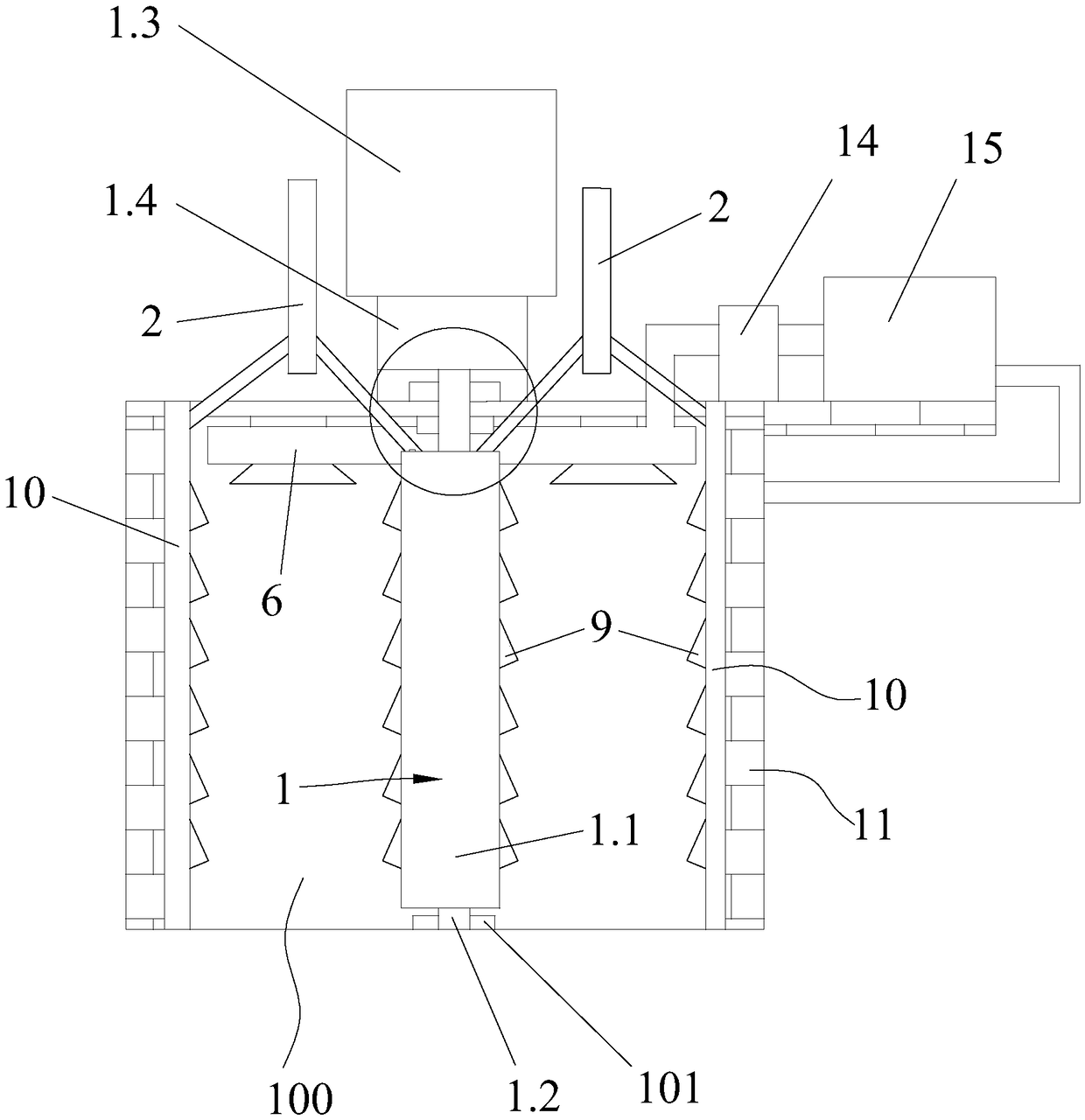
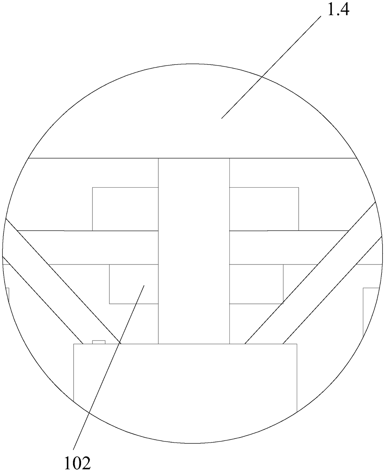
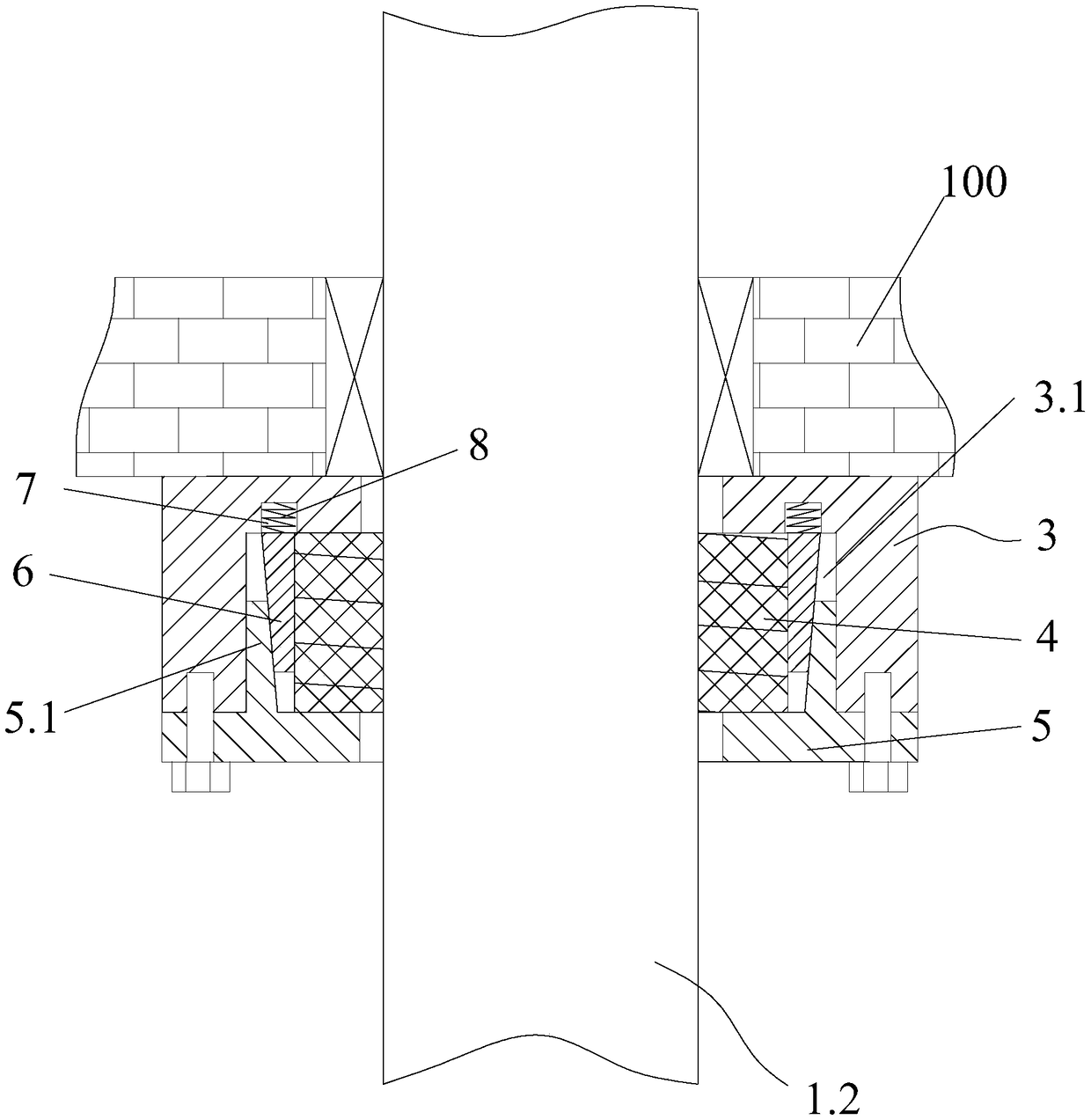
[0028] The present invention will be further described below in conjunction with the accompanying drawings and specific embodiments.

[0029] In the description of the present invention, it should be noted that the terms "top", "outside", "middle position", "bottom surface", "lower end", "upper end", "upper surface", "lower end surface", The orientation or positional relationship indicated by "upper end", "oblique downward direction", "inwardly" and so on are based on the orientation or positional relationship shown in the drawings, and are only for the convenience of describing the present invention and simplifying the description, rather than indicating or It should not be construed as limiting the invention by implying that a referenced device or element must have a particular orientation, be constructed, and operate in a particular orientation.

[0030] In the description of the present invention, it should be noted that unless otherwise specified and limited, the terms "c...


PUM


Abstract

The invention discloses a ceramic packing air drying room. The ceramic packing air drying room comprises an air drying room main body, a rotary air outlet device with the top communicating with an airinlet pipeline is arranged in the air drying room main body, the rotary air outlet device comprises an air outlet pipe, a rotary shaft, a motor and a speed reducer, the rotary shaft is arranged in the middle of the air drying room main body in a rotating mode in the vertical direction, a plane bearing is arranged on the bottom surface of the air drying room main body, the lower end of the rotaryshaft is connected to the plane bearing in a rotating mode, the motor and the speed reducer are both arranged at the top of the air drying room main body, one end of the speed reducer is connected with an output shaft of the motor, the other end of the speed reducer is connected with the upper end of the rotary shaft, and an air sealing mechanism is arranged between the rotary shaft and the top ofan inner cavity of the air drying room main body. According to the disclosed ceramic packing air drying room, air drying hot air is provided for the interior of an air drying room cavity through therotary air outlet device, the hot air is continuously and uniformly conveyed through the rotating device, so that the air drying efficiency is effectively improved, moreover, the sealing performance of the top of the rotary air outlet device is good, air leakage of a rotary portion is avoided.

Description

technical field [0001] The invention relates to the technical field of ceramic filler drying and water removal, in particular to a ceramic filler air-drying room. Background technique [0002] Chemical packing is the basic component of gas-liquid contact in the packed tower. It is widely used in many industries. It has excellent acid and heat resistance, and can resist the corrosion of various inorganic acids, organic acids and organic solvents except hydrofluoric acid. It can be used in It is used in various high and low occasions, and its performance is the main factor determining the operation performance of the packed tower. Among them, the corrugated packing sheet is the most commonly used structured packing in chemical packing towers such as absorption towers. The corrugated packing sheet is mostly made of metal sheet or wire mesh, plastic sheet or plastic mesh and other materials, and its corrugated section is triangular. , The corrugated channels are usually arrange...

Claims


Application Information

Patent Timeline
IPC IPC(8): F26B9/02F26B21/00F26B25/02F26B25/12
CPCF26B9/02F26B21/004F26B25/02F26B25/12
Inventor 李亿明
Owner 李亿明
Why Eureka
Try Eureka