A novel PFC inductor and a manufacturing method thereof

A new type of inductor technology, applied in the field of inductors, can solve the problems of large volume, large distributed capacitance, and inconvenient production of PFC inductors, and achieve the effects of increasing heat dissipation, reducing distributed capacitance, and improving power efficiency

Pending Publication Date: 2019-01-08
惠州佳扬电子科技有限公司
View PDF0 Cites 8 Cited by
  • Summary
  • Abstract
  • Description
  • Claims
  • Application Information

AI Technical Summary

Problems solved by technology

[0002] PFC circuit is an indispensable part of power electronic circuit, and PFC inductors are getting more and more attention; traditional PFC inductors are installed vertically on a fixed aluminum plate after the magnetic core is directly wound with copper wire, and the coil and the aluminum plate pass through the steel strip. Fixed, this kind of inductor is because the magnetic core is integrated, the magnetic core cannot be directly wound by the winding machine when winding the wire, which is inconvenient to manufacture, and the PFC inductor made is relatively large in size, large in distributed capacitance, poor in EMC effect, and heat dissipation poor effect

Method used


Image

  • A novel PFC inductor and a manufacturing method thereof
  • A novel PFC inductor and a manufacturing method thereof
  • A novel PFC inductor and a manufacturing method thereof

Examples


Embodiment 1

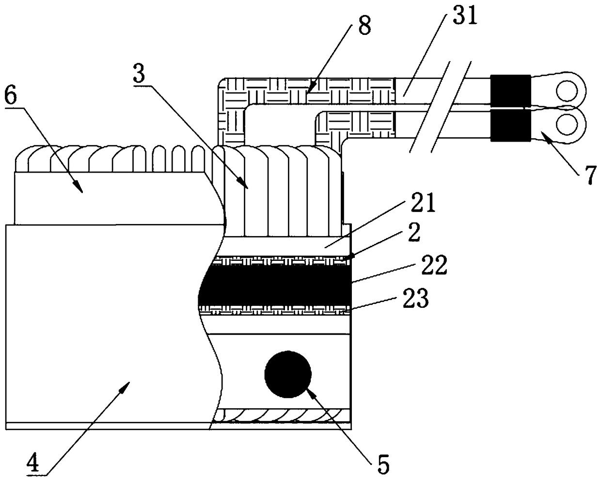
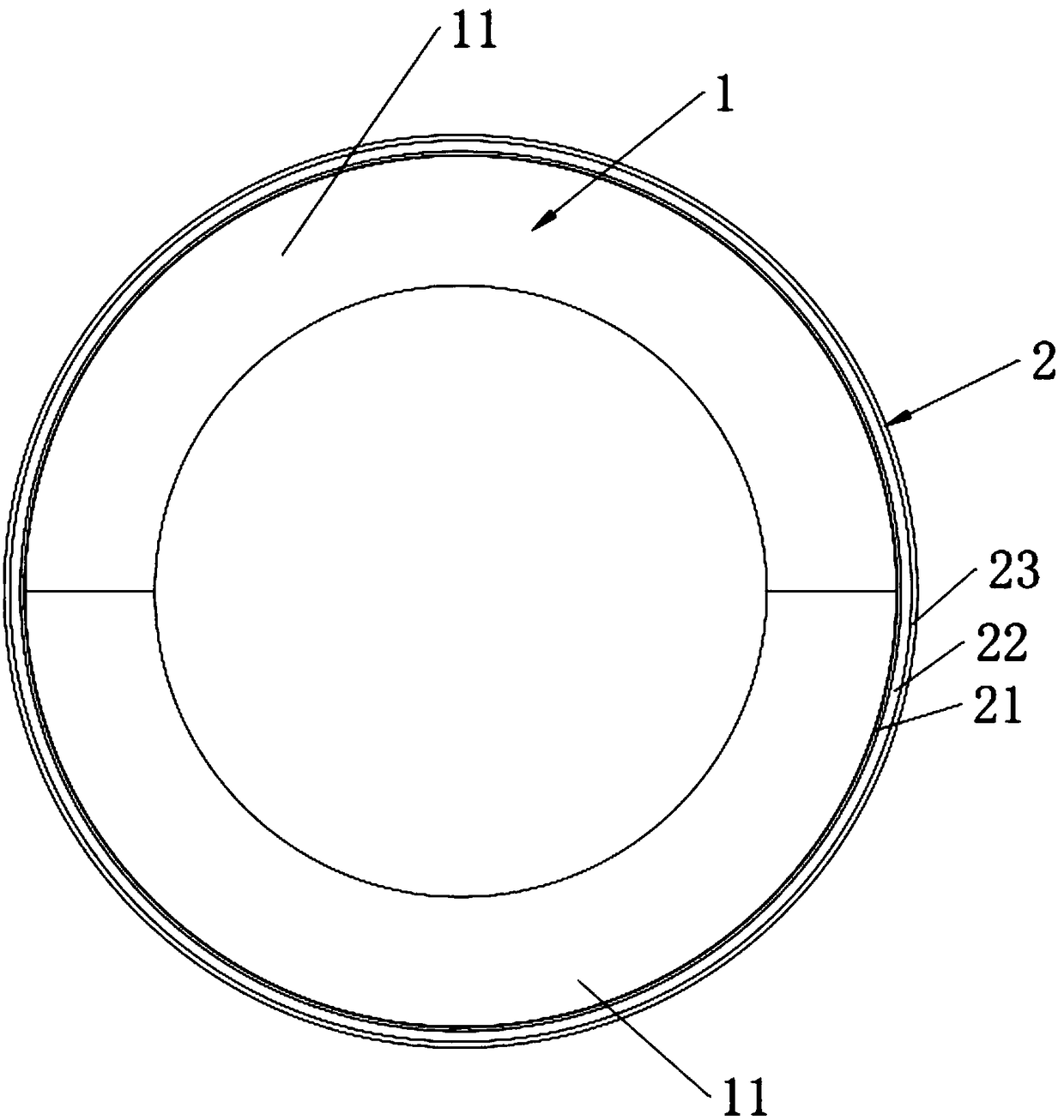
[0041] refer to Figure 1 to Figure 3 , figure 1 It is a structural schematic diagram of the novel PFC inductor in embodiment 1, figure 2 It is a top view of the combined magnetic core and insulating fixture in Embodiment 1, image 3 It is a cross-sectional view of the combined magnetic core in Embodiment 1. The new PFC inductor in this embodiment includes a combined magnetic core 1 , an insulating fixture 2 , a flat copper wire 3 , an aluminum box 4 , a thermally conductive silica gel 5 , a third insulating paper 6 , a crimping terminal 7 and a high-temperature-resistant heat-shrinkable sleeve 8 .

[0042] The combined magnetic core 1 includes two sub-cores 11, the two sub-cores 11 are matched, and the two sub-cores 11 are correspondingly fixed. Each sub-core 11 includes successively laminated silicon-aluminum core layers and iron-silicon core layers. In this embodiment, the thickness of the sendust core layer is 1 to 2 times the thickness of the iron-silicon core layer. ...

Embodiment 2

[0052] refer to Figure 4 , Figure 4 It is a flow chart of the method for preparing a novel PFC inductor in Example 2, and the method for preparing a novel PFC inductor in this embodiment includes the following steps:

[0053] A combined magnetic core 1 is produced, and the combined magnetic core 1 includes two matched sub-magnetic cores 11 . The step of making the combined magnetic core 1 includes the following sub-steps: firstly, two sendust core layers and one sendust core layer are superimposed on each other, and then glued to form the combined magnetic core 1, and the combined magnetic core 1 is along its own Radially cut into two sub-cores 11, in this embodiment, when cutting, cut along the center of the combined magnetic core 1, so that the combined magnetic core 1 is cut into two sub-cores 11 equally divided, so that the sub-magnetic Core 11 Consistency. Specifically, the cutting of the combined magnetic core 1 can be realized by a cutting machine.

[0054] The fl...


PUM


Abstract

The invention discloses a novel PFC inductor, which comprises a combined magnetic core, an insulating fixture and a flat copper wire. The combined magnetic core comprises two matched sub-magnetic cores, and the two sub-magnetic cores are fixedly connected with each other. The insulating fixture comprises a first insulating paper, a steel strip and a second insulating paper, wherein the first insulating paper, the steel strip and the second insulating paper are sleeved on the outside of the combined magnetic core from the inside and the outside in turn; Flat cop wire is vertically wound aroundtwo sub-magnetic cores and an insulate fixture; The present application also provides a method for preparing a novel PFC inductor. After one layer of flat copper wire is vertically wound, the invention is assembled on two sub-magnetic cores, which is convenient to operate. The two sub-magnetic cores are fixedly connected into a combined magnetic core correspondingly, and the flat copper wire formsa complete coil. The PFC inductance distribution capacitance is reduced, the efficiency is improved, and the heat dissipation effect of the PFC inductance is also increased.

Description

technical field [0001] The invention relates to the technical field of inductors, in particular to a novel PFC inductor and a manufacturing method thereof. Background technique [0002] PFC circuit is an indispensable part of power electronic circuit, and PFC inductors are getting more and more attention; traditional PFC inductors are installed vertically on a fixed aluminum plate after the magnetic core is directly wound with copper wire, and the coil and the aluminum plate pass through the steel strip. Fixed, this kind of inductor is because the magnetic core is integrated, the magnetic core cannot be directly wound by the winding machine when winding the wire, which is inconvenient to manufacture, and the PFC inductor made is relatively large in size, large in distributed capacitance, poor in EMC effect, and heat dissipation poor effect. Contents of the invention [0003] Aiming at the deficiencies of the prior art, the invention provides a novel PFC inductor and a pre...

Claims


Application Information

Patent Timeline
Patent Type & Authority Applications(China)
IPC IPC(8): H01F27/02H01F27/08H01F27/22H01F27/24H01F27/26H01F27/28H01F27/29H01F27/32H01F41/00
CPCH01F27/263H01F27/02H01F27/022H01F27/08H01F27/22H01F27/24H01F27/28H01F27/29H01F27/324H01F41/00
Inventor 黄艳红吴嘉洁
Owner 惠州佳扬电子科技有限公司
Why Eureka
Try Eureka