
Energy Internet System

An energy Internet and energy technology, applied in the energy industry, AC networks with different sources of the same frequency, AC network circuits, etc., can solve problems such as inability to meet energy demand and small energy supply radius

Pending Publication Date: 2019-01-08
北京亿利智慧能源科技有限公司 +1
View PDF0 Cites 12 Cited by
  • Summary
  • Abstract
  • Description
  • Claims
  • Application Information

AI Technical Summary

Problems solved by technology

However, due to the small energy supply radius of the existing distributed energy stations, they cannot meet all energy demands

Method used


Image

  • Energy Internet System
  • Energy Internet System
  • Energy Internet System

Examples


Embodiment Construction

[0023] Specific embodiments of the present disclosure will be described in detail below in conjunction with the accompanying drawings. It should be understood that the specific embodiments described here are only used to illustrate and explain the present disclosure, and are not intended to limit the present disclosure.

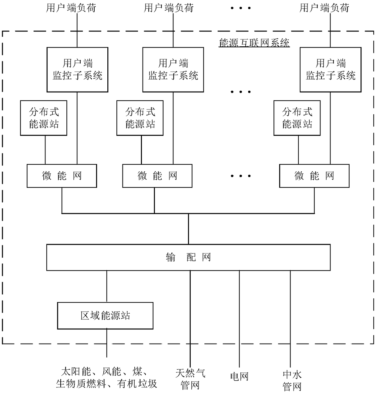
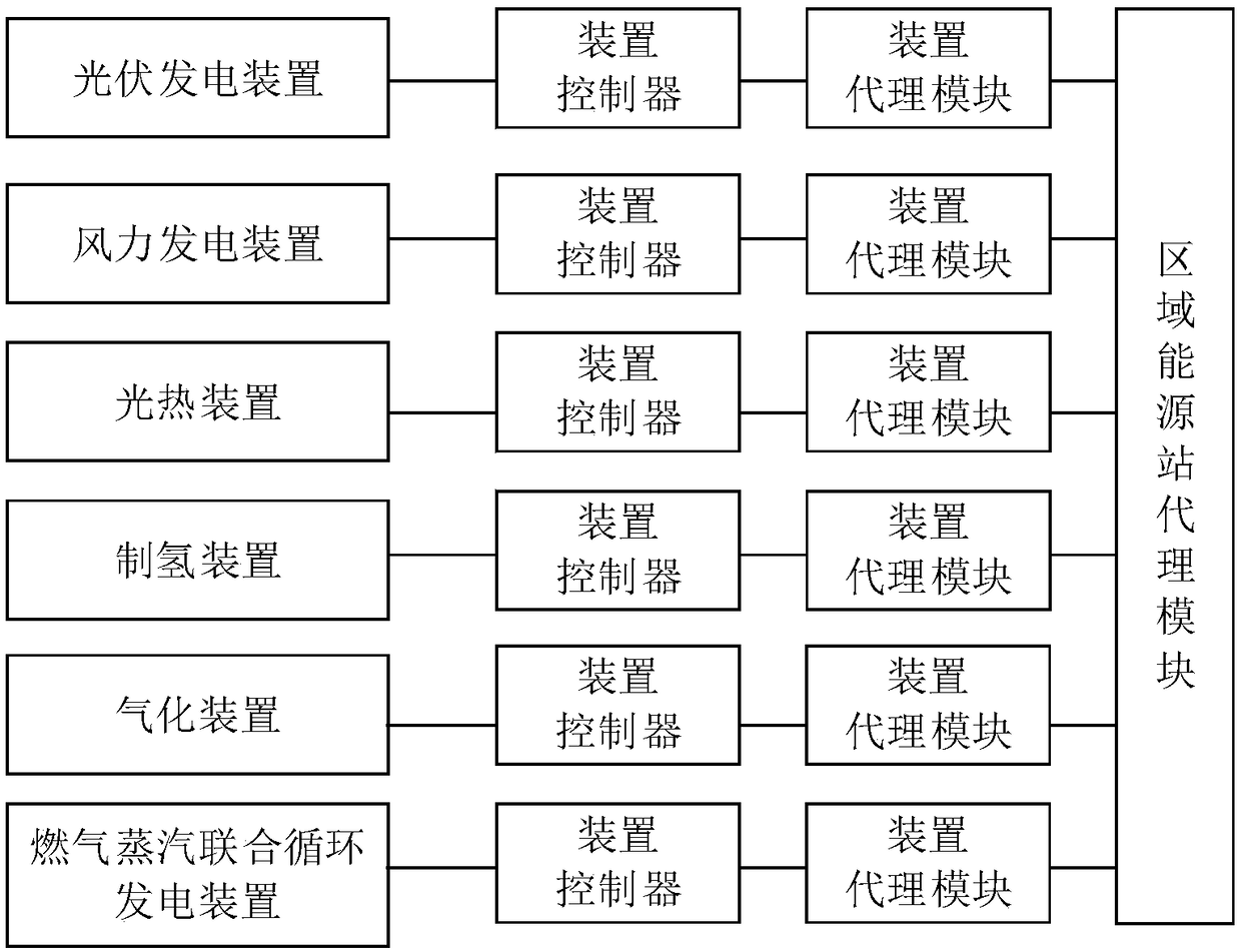
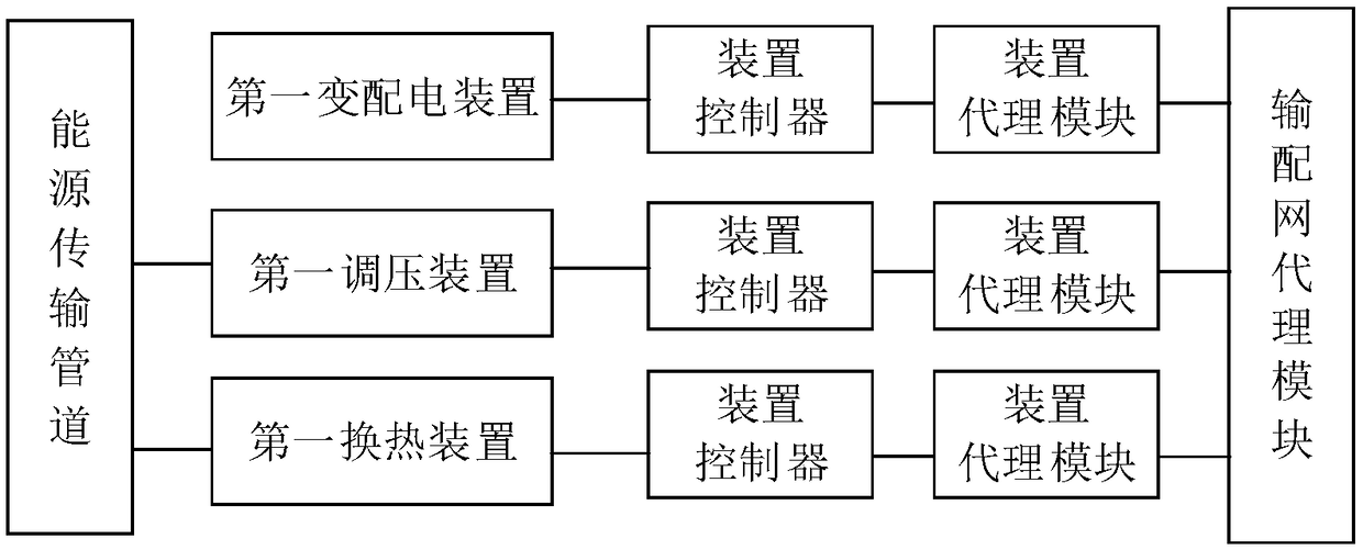
[0024] figure 1 It is a schematic structural diagram of an energy internet system provided by an exemplary embodiment. Such as figure 1 As shown, the subsystems of the Energy Internet system include regional energy stations, transmission and distribution networks, multiple micro-energy networks, multiple distributed energy stations, and multiple user-end monitoring subsystems, and each subsystem includes multiple devices.

[0025] Regional energy stations are used to generate multiple energy media by using one or more of solar energy, wind energy, coal, biomass fuel, organic waste, and natural gas.

[0026] The transmission and distribution network is conn...


PUM


Abstract

The present disclosure relates to an energy Internet system. A subsystem of the system includes: a regional energy station for producing a plurality of energy media using one or more of solar energy,wind energy, coal, biomass fuel, organic waste, and natural gas; A transmission and distribution network for transmitting, converting and storing energy media from regional energy stations, power grids, natural gas pipelines and water mains networks; A plurality of micro-energy grids are used for storing, transforming and transferring the energy medium transmitted from the transmission and distribution grids, the corresponding distributed energy stations and other micro-energy grids to the user terminal load or other micro-energy grids; A plurality of client monitoring subsystems correspondingto the plurality of micro energy networks; A plurality of distributed energy stations corresponding to the plurality of micro-energy grids; Multi-agent system. In this way, the energy generated by the regional energy stations is transported to a plurality of micro-energy grids through a transmission and distribution network, and the energy and information between the plurality of micro-energy grids are interconnected, and each micro-energy grid can be connected with the transmission and distribution network or operated off-grid.

Description

technical field [0001] The present disclosure relates to the fields of energy systems, information systems, and control systems, and in particular, relates to an energy internet system. Background technique [0002] Most of the traditional energy technologies are centralized and large-scale supply models, such as thermal power plants, thermal power plants, district central heating, small-scale central cooling, decentralized cooling technology and other production systems. Centralized energy supply is usually a "one plant, one station, one energy" model, which is convenient for centralized management, but the distance from the user end is relatively long, the loss of energy transmission is large, and the energy supply is single, which cannot guarantee safety and reliability. [0003] Distributed, miniaturized energy production and supply methods have emerged in recent years. This kind of distributed energy station is generally built in the energy load center, applying the pr...

Claims


Application Information

Patent Timeline
Patent Type & Authority Applications(China)
IPC IPC(8): H02J3/06H02J3/38H02J3/28
CPCH02J3/06H02J3/28H02J3/381H02J3/388Y02P80/20
Inventor 张超徐家彬林凯郑阳王丹阳
Owner 北京亿利智慧能源科技有限公司
Learn More