Method and device for treating tail gases of ammonia tanks of coking plant

A tail gas treatment and tail gas technology, applied in gas treatment, chemical instruments and methods, separation methods, etc., can solve problems such as increased cost burden, waste, complex process equipment, etc., and achieve the effect of improving the level of governance and reducing production costs

Pending Publication Date: 2019-01-11
山东环达环保科技有限公司
View PDF0 Cites 6 Cited by
  • Summary
  • Abstract
  • Description
  • Claims
  • Application Information

AI Technical Summary

Problems solved by technology

[0002] As we all know, the existing treatment technology used in the treatment of tail gas emissions from ammonia tanks in coking plants needs to consume a lot of energy or generate a lot of hazardous waste and cause waste of resources, which adds a lot of cost burden to production
[0003] Each ammonia tank in the coking plant will produce a large amount of ammonia-based waste gas, which will cause pollution if it is directly discharged into the atmosphere. The existing process equipment generally includes pickling, alkali cleaning, activated carbon adsorption, RCO, RTO, etc. First, the process and equipment are relatively complicated, and some of them also produce a large amount of hazardous waste, etc., and the treatment cost is high. Secondly, the waste gas after treatment is generally discharged into the atmosphere after reaching the standard, and the utilization rate is low.

Method used


Image

  • Method and device for treating tail gases of ammonia tanks of coking plant
  • Method and device for treating tail gases of ammonia tanks of coking plant

Examples


Embodiment Construction

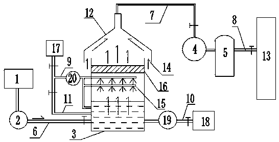
[0025] A coking plant ammonia tank tail gas treatment device as shown in the figure, it includes tail gas collection port 11, fan 2, water-soluble ammonia gas collection tank 3, gas compressor 4, high-pressure storage tank 5, water-soluble ammonia gas collection The bottom of the tank 3 is provided with an air inlet connected to the fan 2, and the tail gas collection port 1 is connected to each ammonia tank to collect ammonia tail gas, and the tail gas is introduced into the bottom of the water-soluble ammonia gas-collecting tank 3 through the fan 2 and the pipeline I6 for water-soluble ammonia removal. The upper part of the water-soluble ammonia gas collection tank 3 is provided with a gas collector 12, and the gas released after the water-soluble ammonia gas collection tank 3 dissolves ammonia is mixed with the gas collector 12 and air, and then connected to the gas compressor 4 through the pipeline II7, and the gas compressor 4 The gas is compressed into the high-pressure st...


PUM


Abstract

The invention discloses a method and a device for treating tail gases of ammonia tanks of a coking plant. All tail gases of ammonia tanks of the coking plant are treated and then are directly used ina regeneration tower for production. The device comprises a tail gas collection port, a fan, a water dissolving and ammonia collecting gas tank, a gas compressor and a high-pressure storage tank whichare sequentially connected, a gas inlet is arranged at the bottom of the water dissolving and ammonia collecting gas tank and is connected with the fan, the tail gases are introduced to the bottom ofthe water dissolving and ammonia collecting gas tank through the fan and a pipeline and undergo water dissolving ammonia removal, a gas collector is arranged at the upper part of the water dissolvingand ammonia collecting gas, a gas released after dissolving ammonia in the tail gases with water in the water dissolving and ammonia collecting gas tank rises to the gas collector, is mixed with air,and then is connected with the gas compressor through a pipeline II, the gas compressor compresses the gas into the high-pressure storage tank for storage, and the high-pressure storage tank substitutes an compressor station to supply the gas to the regeneration tower. The whole method and the device have the advantages of reasonable constitution, maximal utilization of resources of the coking plant without or slightly increasing the energy consumption, effectiveness in treatment of the tail gases of the ammonia tanks, and achieving of the purposes of energy saving and consumption reduction.

Description

technical field [0001] The invention relates to a coking plant waste gas treatment technology, in particular to a coking plant ammonia tank tail gas treatment method and device. Background technique [0002] As we all know, the existing treatment technology used in the treatment of tail gas emissions from ammonia tanks in coking plants needs to consume a lot of energy or generate a lot of hazardous waste and cause waste of resources, which adds a lot of cost burden to production. [0003] Each ammonia tank in the coking plant will produce a large amount of ammonia-based waste gas, which will cause pollution if it is directly discharged into the atmosphere. The existing process equipment generally includes pickling, alkali cleaning, activated carbon adsorption, RCO, RTO, etc. First, the technological process and equipment are relatively complicated, and some also produce a large amount of hazardous waste, etc., and the treatment cost is high. Second, the waste gas after treat...

Claims


Application Information

Patent Timeline
Patent Type & Authority Applications(China)
IPC IPC(8): B01D53/18
CPCB01D53/1406B01D53/18B01D2257/406
Inventor 彭圭
Owner 山东环达环保科技有限公司
Why Eureka
Try Eureka