Marine low-speed diesel exhaust gas collecting tank with catalytic denitration function

A catalytic denitrification and gas collection box technology, applied in gas treatment, mechanical equipment, combustion engines, etc., can solve the problems of consumption, low utilization rate of residual heat, and low economic efficiency, so as to improve denitrification efficiency, facilitate cleaning, Efficient NOx removal effect

Inactive Publication Date: 2019-01-11
HARBIN ENG UNIV
View PDF10 Cites 6 Cited by
  • Summary
  • Abstract
  • Description
  • Claims
  • Application Information

AI Technical Summary

Problems solved by technology

But this method will lead to the consumption of extra energy, the economy is not high, and the utilization rate of residual heat is not high at the same time

Method used


Image

  • Marine low-speed diesel exhaust gas collecting tank with catalytic denitration function
  • Marine low-speed diesel exhaust gas collecting tank with catalytic denitration function
  • Marine low-speed diesel exhaust gas collecting tank with catalytic denitration function

Examples


Embodiment 1

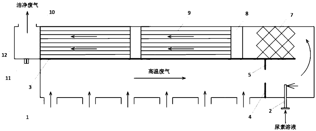
[0047] Such as figure 1 As shown: the top-mounted gas collection box adopts a square structure, and is divided into upper and lower chambers by welding the plate 3 into the gas collection box. The exhaust gas inlet 1 at the bottom of the lower chamber is connected to the exhaust manifold of each cylinder to circulate the exhaust gas, and the upper baffle 5, the lower baffle 4 and the urea injection head 2 are installed in sequence on the right side to prevent the backflow of the reaction gas. The urea injection system is connected, a static mixer 7 is arranged in the upper chamber, and a double-layer catalytic denitrification module 9 is installed. The exhaust gas outlet 10 facing upward on the left side is connected to the turbine, and a soot blower 12 is installed at the lower end of the exhaust gas outlet.

Embodiment 2

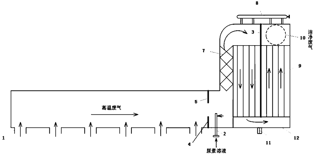
[0049] Such as figure 2 Shown: a side-mounted gas collection box, the left chamber adopts a square structure, and the bottom exhaust gas inlet 1 is connected to the exhaust manifold of each cylinder to circulate the exhaust gas. The baffle 4 and the urea injection head 2; the right chamber also adopts a square structure, the inlet is arranged with a static mixer 7, and then a double-layer catalyst module 9 is arranged, and the double-layer catalyst module 9 is divided into two pieces by the plate 3 to deflect the exhaust gas , improve denitrification efficiency. The exhaust gas outlet 10 connected to the turbine and the soot blowing system 8 are arranged above the right chamber, and the soot blowing box 12 is arranged below the right chamber.

Embodiment 3

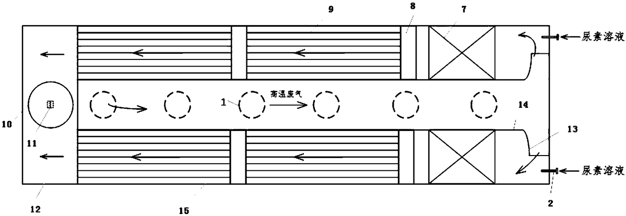
[0051] Such as Figure 3-4 As shown: the ring-mounted gas collection box adopts a circular structure, the inner circular pipe 14 is arranged in the center of the gas collection box, and its bottom is connected with the exhaust manifold of each cylinder, and the tail end of the inner circular pipe 14 adopts the structure of an elbow 13 , waste gas is passed into the outer circular pipe 15. The urea injection head 2 and the static mixer 7 are sequentially installed behind the exhaust gas outlet of the inner circular pipe 14; the outer circular pipe 15 is arranged with an annular denitrification module. The outlet of the exhaust gas of the outer circular pipe 15 opens upwards to prevent the outflow of exhaust gas from entering the turbine with debris; the soot blowing system 8 is arranged on the upper layer of the denitrification module, which can be cleaned regularly.

[0052] In summary: the purpose of the present invention is to provide a marine low-speed diesel engine exhaus...


PUM


Abstract

The invention provides a marine low-speed diesel exhaust gas collecting tank with a catalytic denitration function. The gas collecting tank comprises a gas collecting box and a catalytic denitration module arranged in the gas collecting box, the exhaust gas inlet of the gas collecting box is connected with the exhaust manifold of every cylinder of a diesel engine, the exhaust gas outlet of the gascollecting box is connected with a turbine, and the catalytic denitration module comprises a urea injector head, a static mixer and a double-layer catalyst module; and exhaust gas is mixed with a urea solution, and the obtained solution goes through the static mixer and the double-layer catalyst module. The gas collecting tank adopting the above configuration has the advantages of simple structure, easiness in arrangement, and improvement of the system compactness of the gas collecting tank; a baffle plate is mounted behind an exhaust gas flow to effectively prevent a reaction gas from flowing back into the cylinders, the high temperature of the exhaust gas is used to preheat the catalytic denitration module in order to improve the residual heat utilization rate of the exhaust gas, and the exhaust gas enters an upper chamber from a lower chamber in a baffling manner under high-temperature and high-pressure conditions in order to reduce the linear velocity, so efficient removal of NOxin the exhaust gas is achieved.

Description

technical field [0001] The invention relates to a low-speed diesel engine exhaust gas collection box, in particular to a marine low-speed diesel engine exhaust gas collection box with catalytic denitrification function. Background technique [0002] Because ship pollutants have caused serious damage to the atmosphere and marine environment, countries and international organizations (IMO) around the world have successively formulated regulations to limit the discharge of pollutants. The International Maritime Organization stipulates that after 2016, the NOx emission limit of low-speed diesel engines will be reduced to 3.4g / (KW·h) in the designated emission control area (ECA). At the same time, the Ministry of Transport of my country has also set up the Pearl River Delta, the Yangtze River Delta, and the Bohai Rim (Beijing-Tianjin-Hebei) waters as ships to set up ship air pollutant emission control areas to control the discharge of ship pollutants in my country. [0003] At p...

Claims


Application Information

Patent Timeline
Patent Type & Authority Applications(China)
IPC IPC(8): B01D53/94B01D53/56
CPCB01D53/9418B01D2258/012Y02T10/12
Inventor 朱元清夏冲周松冯永明
Owner HARBIN ENG UNIV
Why Eureka
Try Eureka