A kind of additive manufacturing method of simultaneous heat treatment

A kind of additive manufacturing and laser technology, applied in the field of additive manufacturing, can solve the problems of large energy loss, increased ceramic phase or alloy element burning loss, low efficiency, etc., to achieve the effect of reducing stress, cooling speed and ensuring performance

Active Publication Date: 2020-01-03
HUAZHONG UNIV OF SCI & TECH
View PDF11 Cites 0 Cited by
  • Summary
  • Abstract
  • Description
  • Claims
  • Application Information

AI Technical Summary

Problems solved by technology

The process used in laser remelting is similar to that of the solid body, and the solid body is remelted, with low efficiency and large energy loss, and remelting will increase the burning loss of the ceramic phase or alloy elements in the solid body

Method used


Image

  • A kind of additive manufacturing method of simultaneous heat treatment

Examples


Embodiment 1

[0032]In this embodiment, AlSi10Mg / Al is formed 2 o 3 Composite materials are taken as an example for illustration, which includes the following steps:

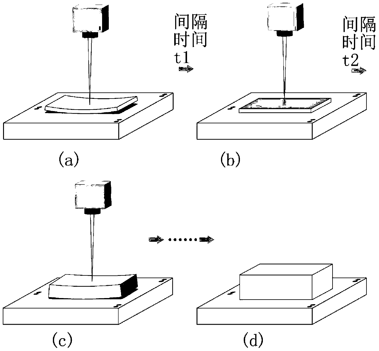
[0033] S1 Laying of AlSi with a thickness of 20 μm 10 Mg / Al 2 o 3 Composite powder, the powder spreading time is 10s, the powder is melted and formed with 200W laser power, 200mm / s scanning speed, and 0.12mm scanning distance, and the scanning process of one layer is completed. Due to the large temperature gradient and internal stress in the forming process , will cause slight stress deformation of the entity, and even edge cracking;

[0034] After an interval of 1s in S2, reheat the completed layer with 100W laser power, 1200mm / s scanning speed, and 0.12mm scanning distance to play the role of post-heating to reduce the cooling rate when SLM forming cermet materials, but not melt formed layers;

[0035] S3 Repeating steps S1 and S2, the edge of the final formed solid will not be cracked due to stress, and a dense part ...

Embodiment 2

[0037] This embodiment takes the forming of AlSi10Mg / SiC material as an example for illustration, which includes the following steps:

[0038] S1 lays AlSi10Mg / SiC composite powder with a thickness of 40μm, and the powder laying time is 5s. The powder is melted and formed with 2000W laser power, 3000mm / s scanning speed, and 0.08mm scanning distance to complete the scanning process of one layer. There is a large temperature gradient and internal stress, which will cause slight stress deformation of the entity, and even edge cracking;

[0039] After an interval of 0.2s in S2, reheat the completed layer with 200W laser power, 2000mm / s scanning speed, and 0.12mm scanning distance to play the role of afterheating and reduce the cooling rate when SLM forms cermet materials, but does not melt formed layers;

[0040] S3 Repeating steps S1 and S2, the edge of the final formed solid will not be cracked due to stress, and a dense part with good shape and quality can be obtained, and the...

Embodiment 3

[0042] This embodiment takes forming IN718 superalloy material as an example for illustration, which includes the following steps:

[0043] S1 lays metal powder with a thickness of 30μm, and the powder laying time is 8s. The powder is melted and formed with 390W laser power, 1000mm / s scanning speed, and 0.1mm scanning distance to complete the scanning process of one layer. The temperature gradient and internal stress will cause the entity to have slight stress deformation and even edge cracking;

[0044] S2: After an interval of 0.5s, reheat the completed layer with 100W laser power, 3000mm / s scanning speed, and 0.1mm scanning distance to play the role of afterheating, but do not melt the formed layer;

[0045] S3 repeating steps S1 and S2, finally forming a dense part with no cracks on the edge of the solid body and good shape and quality, and the density reaches more than 99.9%.


PUM

PropertyMeasurementUnit
thicknessaaaaaaaaaa
thicknessaaaaaaaaaa

Abstract

The invention belongs to the technical field of additive manufacturing, and specifically discloses an additive manufacturing method of synchronous heat treatment, which includes the following steps: S1 laying powder, laser scans the powder according to a preset scanning path, and completes the laser scanning of the current layer Processing; S2 reheats the processed current layer with a low-power laser after a certain time interval; S3 repeats steps S1 and S2 to complete the laser scanning processing of all layers to obtain the required dense parts. The invention reduces the cooling speed of the material during forming, increases the existence time of the molten pool, reduces the formation of cracks and holes, and can be used for laser additive manufacturing of metal and cermet composite materials.

Description

technical field [0001] The invention belongs to the technical field of additive manufacturing, and more specifically relates to an additive manufacturing method for simultaneous heat treatment. Background technique [0002] Metal / cermet has been widely used in the aerospace field, and its traditional preparation process is complicated and the manufacturing cycle is long. As a rapid prototyping method, laser additive manufacturing technology has been applied in various fields, and can realize short-cycle rapid prototyping of complex parts. In the laser additive manufacturing process, due to the extremely fast cooling rate, a large temperature gradient and internal stress are generated inside the formed part, causing the part to warp, deform or even crack, making the processing process fail. In addition, the existence time of the molten pool is short, the fluidity of the molten metal is insufficient, and it is difficult to achieve dense forming. [0003] A lot of research ha...

Claims


Application Information

Patent Timeline
Patent Type & Authority Patents(China)
IPC IPC(8): B22F3/105B22F3/24B33Y10/00B33Y40/00
CPCB22F3/24B33Y10/00B33Y40/00B22F2003/248B22F10/00B22F10/38B22F10/25B22F10/364B22F10/28Y02P10/25
Inventor 廖海龙朱海红薛刚刘诗文张文奇张长春曾晓雁
Owner HUAZHONG UNIV OF SCI & TECH
Why Eureka
Try Eureka