Biological denitrification treatment device and method for wastewater

A technology of biological denitrification and treatment device, which is applied in sustainable biological treatment, water/sludge/sewage treatment, water pollutants, etc. Problems such as a large number of equipment, to achieve the effect of reducing the number of moving equipment, reducing complexity, and simplifying the control system

Pending Publication Date: 2019-01-11
SHANGHAI LANKE PETROCHEM ENG & TECH
View PDF0 Cites 0 Cited by
  • Summary
  • Abstract
  • Description
  • Claims
  • Application Information

AI Technical Summary

Problems solved by technology

However, in the existing combined process, the adjustment space is small, and it is difficult to adapt to the working conditions of major changes in the influent water quality; and the aeration / flushing air pipe system is complex and the number of moving equipment is large, resulting in high construction investment costs and operating energy consumption ; In addition, the buffer capacity for the instantaneous large-scale water quality changes that may occur in actual working conditions is weak, which affects the overall impact resistance of the system

Method used


Image

  • Biological denitrification treatment device and method for wastewater
  • Biological denitrification treatment device and method for wastewater

Examples


Embodiment 1

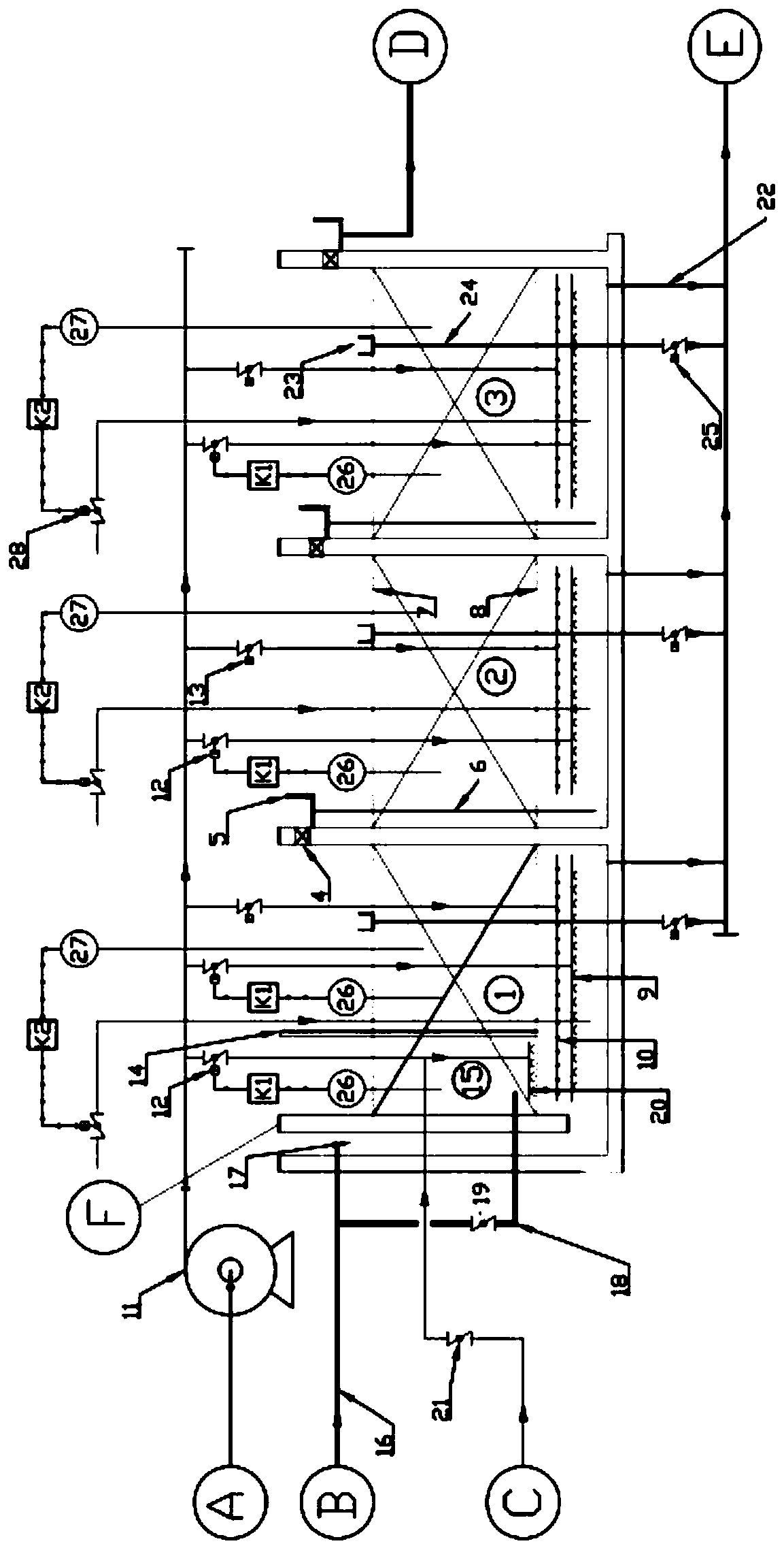
[0057] combine figure 1 As shown, a biological denitrification treatment device for wastewater includes three-stage series reaction pools 1 / 2 / 3, and the top of the partition wall at the end of each reaction pool is provided with a water outlet 4, and the height of the water outlet 4 is lower than that of the reaction pool. The water outlet 4 is provided with a water distribution tank 5; the water tank 5 is provided with a water diversion pipe 6, and for the first and second reaction tanks 1 / 2, the water diversion pipe 6 is used to guide the waste water to the bottom of the next reaction tank , so as to ensure that the waste water enters from the bottom of each level of reaction pool and is discharged from the top. The water tank is connected with the water outlet pipeline, and the treated waste water D is sent out to the device);

[0058] The reaction pool 1 / 2 / 3 of any stage is divided into a reaction area in the middle of the pool body by at least two layers of horizontally ...

Embodiment 2

[0065] In this embodiment, on the basis of Embodiment 1 or its preferred example, a premixing tank 15 is also added in the first-stage reaction tank 1; Water branch pipe 18, the water inlet branch pipe 18 is controlled by a branch valve 19;

[0066] In this embodiment, a premixed tank structure is added in the primary reaction tank, which can effectively alleviate the impact of sudden changes in water quality on the downstream system.

[0067] As a preferred embodiment, the outlet of the water inlet branch pipe 18 is located on the upper side of the lower metal mesh support 8, and a premixing tank aeration pipe 20 is provided below the outlet of the water inlet branch pipe 18, and the premixing tank is aerated. An aeration valve 12 is also provided on the pipe 20 .

[0068] The premix tank aeration pipe 20 in this preferred example is used to centrally aerate the wastewater at the outlet of the water inlet branch pipe 18, and promote the uniform mixing of the wastewater and f...

Embodiment 3

[0072] In this embodiment, on the basis of Embodiments 1 and 2, a dissolved oxygen meter 26 is also provided in the premixing tank 15 and any one of the reaction tanks, and the dissolved oxygen meter 26 and the aeration valve 12 form a dissolved oxygen control loop K1 The dissolved oxygen meter 26 is directly in contact with the water body in each reaction tank, and directly monitors and displays the dissolved oxygen concentration in each reaction tank; the dissolved oxygen concentration in the tank can be adjusted by controlling the aeration valve 12 in the dissolved oxygen control loop K1;

[0073] In the premix tank 15 and any one-stage reaction tank, a pH meter 27 and a dosing regulating valve 28 are also set to form an acid-base control loop K2 ( figure 1 Because the typesetting position is limited, the acid-base control loop in the premixing tank is not drawn); the pH meter 27 is directly in contact with the water body in each reaction tank, and the pH in each reaction ta...


PUM

PropertyMeasurementUnit
diameteraaaaaaaaaa
pore sizeaaaaaaaaaa

Abstract

The invention discloses a biological denitrification treatment device for wastewater. The biological denitrification treatment device comprises three-stage reaction tanks connected in series, the topof a partition wall at the tail end of the reaction tank at any stage is provided with a water outlet, the height of the water outlet is smaller than the height of the reaction tank, a water distribution tank is arranged at the water outlet, the water distribution tank is provided with a water conduit for guiding waste water to the bottom of the next-stage reaction tank or out of the device, the middle of the reaction tank at any stage is divided into reaction zones through several horizontally arranged metal mesh brackets, aeration pipes and flushing gas pipes in the reaction zones share a common air source, one side in the reaction tank at the first stage is provided with a water inlet, and a water feeding main pipe for receiving upstream sewage and an alkali liquid feeds the sewage intothe bottom of the reaction tank at the first stage through the water inlet. The invention also provides a novel method. The device and method are suitable for water feeding under various work conditions and satisfy different treatment requirements and have strong adaptability and stability.

Description

technical field [0001] The invention belongs to the technical field of sewage treatment, and in particular relates to a waste water biological denitrification treatment device and process. Background technique [0002] As the relevant national and local departments have stricter requirements on sewage discharge, the "Petroleum Refining Industry Pollutant Discharge Standard" (GB31570-2015) and "Petrochemical Industry Pollutant Discharge Standard" (GB31571-2015) were released in 2015. ) have put forward stricter requirements on the total nitrogen, ammonia nitrogen and other indicators in sewage treatment. Therefore, it is imperative to develop an efficient and energy-saving denitrification process. [0003] At present, the technology with many application examples is biological denitrification technology, including A / O process, oxidation ditch, short-range nitrification and denitrification, immobilized biological denitrification technology, etc. However, the single use of th...

Claims


Application Information

Patent Timeline
Patent Type & Authority Applications(China)
IPC IPC(8): C02F3/02C02F101/16
CPCC02F3/02C02F2101/16Y02W10/10
Inventor 杜先苗晓亮马洪玺王日彩
Owner SHANGHAI LANKE PETROCHEM ENG & TECH
Why Eureka
Try Eureka