
Household double-plate heat recovery fresh air ventilator unit

A fresh air unit and heat recovery technology, applied in heat recovery systems, space heating and ventilation, space heating and ventilation details, etc., can solve the difficulty of transportation and disassembly, the difficulty of air duct design, and the inability to return wind energy Effective use of other issues to achieve the effect of a simple structure

Pending Publication Date: 2019-01-11
HUNDRED TECH CO LTD
View PDF7 Cites 0 Cited by
  • Summary
  • Abstract
  • Description
  • Claims
  • Application Information

AI Technical Summary

Problems solved by technology

The traditional fresh air unit mainly has the following problems in practical application: it cannot effectively utilize the return air energy, resulting in high energy consumption of the unit and low overall energy efficiency; single function and poor environmental adaptability affect the utilization rate of the unit
Although this integrated fresh air unit can achieve a certain heat recovery function, its structure is relatively complex and its volume is large, which increases the difficulty of the preparation process; especially its air duct is difficult to design due to space constraints, and there are often many Steering at a large angle leads to large wind resistance and affects the balance of fresh air and return air, and its heat recovery efficiency and energy-saving effect are not ideal
At the same time, this integrated fresh air unit is difficult to transport and disassemble, which is not conducive to later inspection and maintenance.

Method used


Image

  • Household double-plate heat recovery fresh air ventilator unit

Examples


Embodiment Construction

[0017] First of all, it needs to be explained that the terminology such as up, down, front, back, left, right, etc. in the present invention are only described in accordance with the accompanying drawings for ease of understanding, and are not intended to limit the technical solutions of the present invention and the scope of protection. .

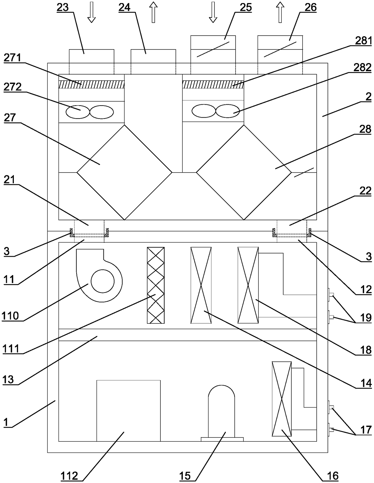
[0018] Such as figure 1 The specific implementation of a household double-plate heat recovery fresh air unit of the present invention is shown, which includes a dehumidification unit and a heat recovery unit. The dehumidification unit is provided with a first casing 1, so that the first casing 1 is provided with a first tuyere 11 and a second tuyere 12 on the left half and right half of its top wall correspondingly, and the inner cavity of the first casing 1 The partition 13 is divided into an upper cavity and a lower cavity. An evaporator 14 is arranged in the upper cavity of the first shell 1, and a compressor 15, a water-cooled condenser...


PUM


Abstract

The invention relates to a household double-plate heat recovery fresh air ventilator unit. The household double-plate heat recovery fresh air ventilator unit comprises a dehumidification unit and a heat recovery unit, the dehumidification unit comprises a first shell body, and a first air opening and a second air opening are formed in the top wall of the first shell body; an inner cavity of the first shell body is divided into an upper cavity and a lower cavity through a partition layer, an evaporator is arranged in the upper cavity, and a compressor, a water-cooled condenser and an expansiondevice are arranged in the lower cavity; and the heat recovery unit comprises a second shell body, a third air opening and a fourth air opening are formed in the bottom wall of the second shell body,the top wall of the second shell body is provided with an air return opening, an air supply opening, a fresh air opening and an exhaust opening, a first plate type heat exchanger and a second plate type heat exchanger which are distributed left and right are arranged in the second shell body, and the first plate type heat exchanger and the second plate type heat exchanger are obliquely arranged. The household double-plate heat recovery fresh air ventilator unit has the advantages of being simple in structure, convenient to assemble and disassemble, reliable in performance and remarkable in energy conservation; and the return air energy is recycled in different stages, so that the overall energy efficiency ratio of the unit is improved.

Description

Technical field [0001] The invention relates to an air conditioner, in particular to a household double-plate heat recovery fresh air unit. Background technique [0002] With the development of economy and society, people have higher and higher requirements for the living environment, which has promoted the rapid development of building energy saving and air-conditioning equipment, and various types of new fan units have appeared. The traditional fresh air unit mainly adopts the heat pump method. In summer, the refrigerant releases heat at the condenser on the one hand and discharges the heat through water cooling or air cooling. On the other hand, it absorbs heat at the evaporator to reduce the fresh air temperature. For the purpose of refrigeration and dehumidification, the fresh air is reheated by the reheater installed at the back of the evaporator to prevent the fresh air temperature from being too low to affect the indoor air quality. In winter, the flow direction of the r...

Claims


Application Information

Patent Timeline
Patent Type & Authority Applications(China)
IPC IPC(8): F24F3/147F24F7/08F24F12/00F24F13/30
CPCF24F3/147F24F7/08F24F12/002F24F13/30Y02B30/56
Inventor 丛旭日
Owner HUNDRED TECH CO LTD
Learn More