Adjoining-pipe liquid spraying defrosting heat source tower heat pump device

A heat source tower heat pump, heat source tower technology, applied in refrigeration and liquefaction, lighting and heating equipment, damage protection and other directions, can solve problems such as miniaturization of unfavorable heat source tower heat pump system and household installation, large space occupation, antifreeze drift and other problems , to overcome the drift after atomization, reduce the space occupied, and solve the effect of drift after atomization

Inactive Publication Date: 2019-01-11
鲍家邻
View PDF0 Cites 3 Cited by
  • Summary
  • Abstract
  • Description
  • Claims
  • Application Information

AI Technical Summary

Problems solved by technology

[0002] The defrosting method of the current heat source tower heat pump system in my country is to spray antifreeze with a special spray device suspended above the heat exchange coil, and to spray antifreeze with a special spray device suspended in the air for large heat source tower heat pump systems. It is better, but if the heat source tower heat pump system is to be miniaturized and householdized, the dedicated spraying device has many disadvantages
First, it takes up a lot of space, including the pressurized water pump, pipes, nozzles and other spraying equipment, which are not conducive to the miniaturization of the heat source tower heat pump system and household installation
The second is the heavy weight. In order to ensure the necessary pressure and flow during spraying, the system must be equipped with a pressurized water pump with larger power, pipes and nozzles with larger diameters. These facilities have larger weight
The third is the problem of antifreeze drift. When the suspended nozzle sprays the antifreeze, more atomized particles are formed. Under the suction of the exhaust fan, these atomized particles will be discharged into the air with the airflow, which will affect the surrounding environment. environmental damage

Method used


Image

  • Adjoining-pipe liquid spraying defrosting heat source tower heat pump device

Examples


Embodiment Construction

[0019] The present invention will be further described in conjunction with the accompanying drawings.

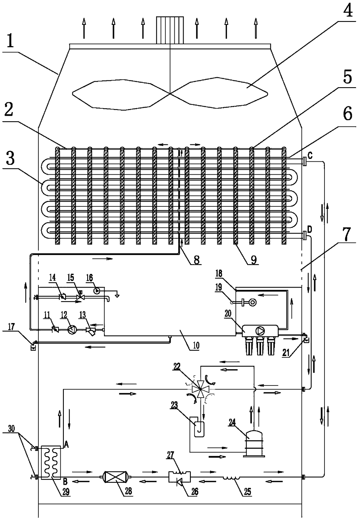
[0020] as attached figure 1 As shown, the present invention includes a heat source tower body 1, a fin accompanying liquid supply pipe 2, a heat exchange coil 3, an exhaust fan 4, several fin accompanying pipes 5, several coil accompanying pipes 6, and a main liquid supply pipe 8 , a number of fins 9, an antifreeze solution pool 10, a liquid supply check valve 11, an antifreeze solution supply pump 12, a filter 13, a replenishment check valve 14, a replenishment solenoid valve 15, a liquid level controller 16, a concentration meter 19, Permeable membrane equipment 20, four-way valve 22, gas-liquid separator 23, compressor 24, capillary, dry filter 28, heat exchanger 29, characterized in that: heat exchange coil 3, exhaust fan 4, antifreeze solution pool 10 , antifreeze solution supply liquid pump 12, filter 13, permeable membrane equipment 20, gas-liquid separator 23, compr...


PUM


Abstract

The invention relates to an adjoining-pipe liquid spraying defrosting heat source tower heat pump device. The adjoining-pipe liquid spraying defrosting heat source tower heat pump device comprises a heat source tower body, a fin adjoining-pipe liquid supply pipe, a heat exchange coil, an exhaust fan, a plurality of fin adjoining-pipes, a plurality of coil adjoining-pipes, a main liquid supply pipe, a plurality of fins, an antifreeze solution pool, a liquid supply check valve, an antifreeze solution liquid supply pump, a filter, a concentration meter, osmotic membrane equipment, a four-way valve, a gas-liquid separator, a compressor, capillary tubes, a drying filter and a heat exchanger. According to the heating condition, a refrigerant is compressed into high-temperature and high-pressuresteam by the compressor and then enters the heat exchanger through the four-way valve. The steam releases heat and condenses in the heat exchanger, and then the refrigerant flows into the drying filter, the dried and filtered refrigerant flows through an auxiliary capillary tube and enters the heat exchange coil, the refrigerant flowing out of the heat exchange coil enters the four-way valve and enters the gas-liquid separator, and the refrigerant is processed by the gas-liquid separator and then enters an air inlet of the compressor from the other outlet of the gas-liquid separator to start the next cycle. Refrigeration condition cycle is opposite to heating condition. The adjoining-pipe liquid spraying defrosting heat source tower heat pump device has the advantages of simple structure,small occupied space, light weight and good defrosting effect.

Description

technical field [0001] The invention relates to a heat source tower heat pump device for liquid spraying and defrosting with pipes, which is mainly suitable for miniaturized and domestic closed heat source tower heat pump systems, and belongs to the technical field of air conditioning and refrigeration. Background technique [0002] The defrosting method of the current heat source tower heat pump system in my country is to spray antifreeze with a special spray device suspended above the heat exchange coil, and to spray antifreeze with a special spray device suspended in the air for large-scale heat source tower heat pump systems. It is better, but if the heat source tower heat pump system is to be miniaturized and householdized, the dedicated spraying device has many disadvantages. One is that it takes up a lot of space, and the sprinkler equipment including pressurized water pumps, pipes and nozzles has a large volume, which is not conducive to the miniaturization of the hea...

Claims


Application Information

Patent Timeline
Patent Type & Authority Applications(China)
IPC IPC(8): F25B47/00
CPCF25B47/00
Inventor 鲍家邻
Owner 鲍家邻
Why Eureka
Try Eureka