

Non-contact device for detecting vibration of aircraft tail and method
A vibration detection, non-contact technology, used in measuring devices, measuring ultrasonic/sonic/infrasonic waves, instruments, etc., can solve problems such as experimental errors and affect experimental accuracy, achieve uncomplicated structure, improve measurement accuracy, and reduce errors. Effect
Pending Publication Date: 2019-01-11
SOUTH CHINA UNIV OF TECH
View PDF11 Cites 1 Cited by
- Summary
- Abstract
- Description
- Claims
- Application Information
AI Technical Summary
Problems solved by technology
[0003] So far, the mainstream vibration detection devices used for the study of aircraft tail buffeting mainly use piezoelectric sensors. This contact measurement method must have a load effect because the detection device is in direct contact with the measured object, so it is introduced into the experiment. error, which affects the accuracy of the experiment
Method used
View moreImage
Smart ImageViewing Examples

Examples
Embodiment
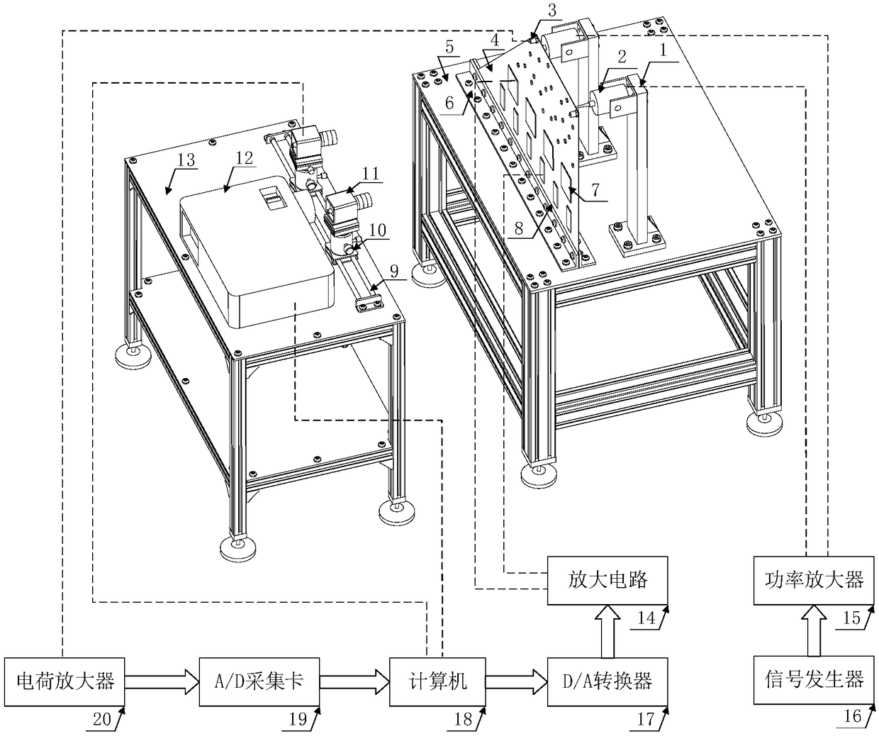
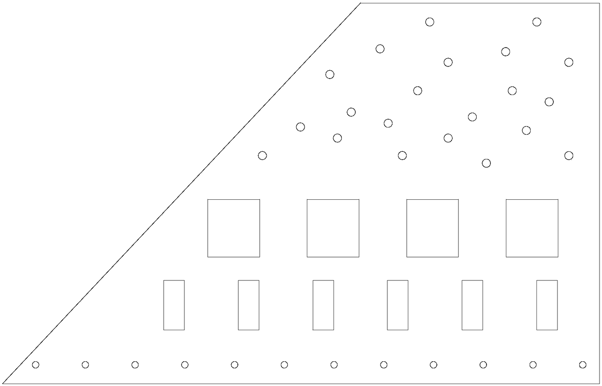
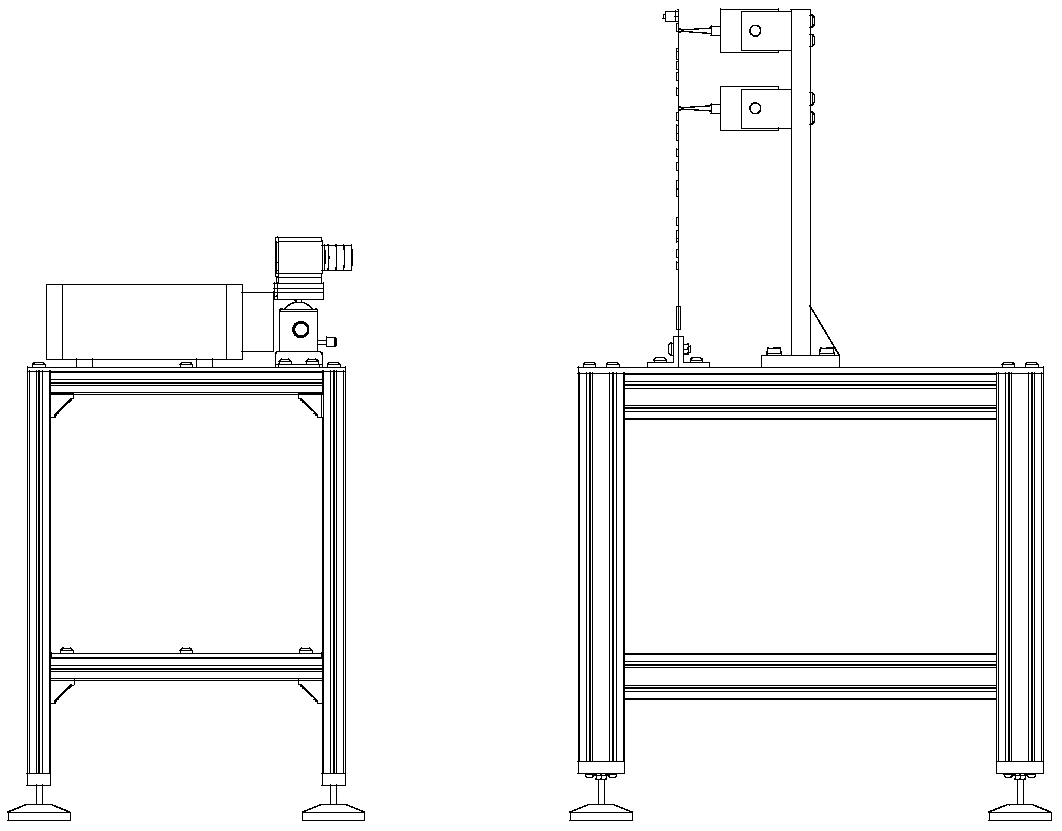
[0039] Such as Figure 1-Figure 5 Shown, a vibration detection device of a non-contact aircraft empennage comprises an aircraft empennage body part, an excitation part, a vibration detection part and a control part;
Login to View More PUM
 Abstract
The invention discloses a non-contact device for detecting the vibration of an aircraft tail and a method. The device comprises an aircraft tail body portion, an excitation portion, a vibration detecting portion and a control portion. The aircraft tail body portion comprises an aircraft tail structure. The excitation portion comprises an exciter, a signal generator, and a power amplifier. The vibration detecting portion comprises a projector, an accelerometer, and a CCD camera. The control portion comprises a piezoelectric ceramic driver, a torsional modal driver, an amplifying circuit, and aD / A converter. According to the non-contact device for detecting the vibration of an aircraft tail and the method, the measurement and control of the vibration of the aircraft tail body portion are realized.
Description
technical field [0001] The invention relates to the field of vibration control of an aircraft empennage, in particular to a vibration detection device and method for a non-contact aircraft empennage. Background technique [0002] Empennage is a device installed on the tail of an aircraft to enhance the stability of the aircraft during flight. One of the damages aircraft tails face during flight is tail buffeting. Aircraft, especially fighter jets, form buffeting when the airflow diffuses through the fuselage and wings at high angles of attack. Buffeting is defined as the irregular vibration of the aircraft structure caused by turbulence. The high-intensity eddy current load will be formed during the flight of the aircraft. This vortex will increase the lift when it passes through the wings and fuselage, but when it encounters the aircraft empennage Occasionally, high-energy turbulent impacts will be generated on the empennage structure, and long-term impacts will form cont...
Claims
Login to View More Application Information
Patent Timeline
 Patent Type & AuthorityApplications(China)
IPC IPC(8): G01H9/00
CPCG01H9/00
Inventor邱志成黄子骞
OwnerSOUTH CHINA UNIV OF TECH