Method for testing residual stress of welding joint based on three-dimensional optical measurement technology and contour method

A measurement technology and three-dimensional optical technology, applied in the field of engineering residual stress measurement, can solve the problems of inability to measure residual stress of workpiece, inability to accurately measure longitudinal stress and transverse stress gradient, time-consuming and other problems

Active Publication Date: 2019-01-11
XI AN JIAOTONG UNIV
View PDF4 Cites 14 Cited by
  • Summary
  • Abstract
  • Description
  • Claims
  • Application Information

AI Technical Summary

Problems solved by technology

However, both of these two commonly used methods measure the surface residual stress and cannot measure the internal residual stress of the workpiece.
Other internal residual stress testing methods, such as the layer-by-layer peeling method and the crack flexibility method, can measure the uniform residual stress distri

Method used


Image

  • Method for testing residual stress of welding joint based on three-dimensional optical measurement technology and contour method
  • Method for testing residual stress of welding joint based on three-dimensional optical measurement technology and contour method
  • Method for testing residual stress of welding joint based on three-dimensional optical measurement technology and contour method

Examples


Embodiment

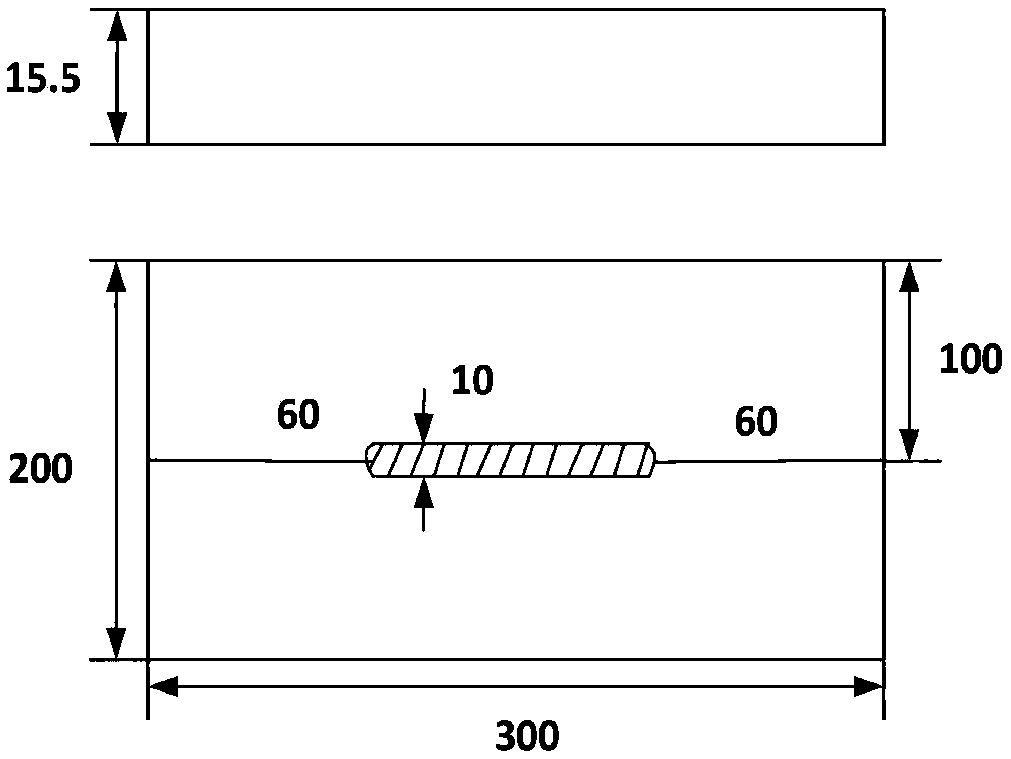
[0045] In this example, if figure 1 As shown, the size of the Q235B steel plate specimen used is 300mm×200mm×15.5mm, and the total length of the weld is 180mm. The experimental inverter DC pulse TIG welding machine WSM-315, the welding torch is fixed on the MOTOMAN six-axis robot to realize automatic welding, using a thoriated tungsten electrode with a diameter of 3.2mm, the tungsten electrode protruding length is 4mm, and the distance between the tip of the tungsten electrode and the test plate The surface is 3mm, the shielding gas is pure argon, the test plate is in an unrestrained state during the welding process, and can be deformed freely. The welding current is 220A, the welding voltage is 17V, and the welding speed is 15cm / min.

[0046] A method for testing the residual stress of welded joints based on three-dimensional optical measurement technology and profilometry, the steps of which are as follows:

[0047] Step 1: Before welding, stress-relief annealing is perform...


PUM


Abstract

Disclosed is a method for testing a residual stress of a welding joint based on a three-dimensional optical measurement technology and a contour method. The method comprises the following steps: performing pre-processing before welding; after welding, performing cutting perpendicular to a cross section of a weld on a welding test plate, and performing XJTU-OM capturing on the cut test plate to obtain calculated measurement point cloud data; marking two cut planes as cutting faces A and B; performing preliminary de-noising fitting on the measurement point cloud data by adopting a Geomagic-qualify extruded scanning data band width to obtain an primary de-noised point cloud; performing de-noising on the primary de-noised point cloud obtained in the step3 according to a mean value of grid sizes by MATLAB, interpolating contour data between points to obtain fitting contours of the cutting faces A and B; performing mirroring on a fitting profile of the cutting face A measured by XJTU-OM, then performing point-by-point averaging on the two cutting faces A and B, generating a model with a displacement deviation by MATLAB for final elasticity calculation; and performing stress calculation and analyzing. The present invention has advantages of having important theoretical and engineering values for testing the residual stress of a weldment.

Description

technical field [0001] The invention relates to the field of engineering measurement residual stress, in particular to a method for testing residual stress of welded joints based on three-dimensional optical measurement technology and contour method. Background technique [0002] Since the development of residual stress testing, there have been dozens of testing methods for different working conditions, which are divided into mechanical (destructive) measurement methods and physical (non-destructive) measurement methods, each of which has its own advantages and disadvantages. The basic principle of destructive measurement of residual stress is to cut off part of the material of the workpiece, the release of residual stress will cause deformation of the cut part, measure the strain at this place, and obtain the magnitude of the residual stress according to Hooke's law. Destructive methods include blind hole method, strip cutting method, elastic deformation method, etc. Among ...

Claims


Application Information

Patent Timeline
IPC IPC(8): G01L5/00G06F17/50
CPCG01L5/0047G06F30/23
Inventor 殷咸青刘珈妤牛靖梁晋张建勋
Owner XI AN JIAOTONG UNIV
Why Eureka
Try Eureka