Carbon coating method for non-carbon anode materials
A negative electrode material, carbon coating technology, applied in the direction of negative electrode, battery electrode, active material electrode, etc., can solve the problem of poor uniformity of carbon coating layer
- Summary
- Abstract
- Description
- Claims
- Application Information
AI Technical Summary
Problems solved by technology
Method used
Image
Examples
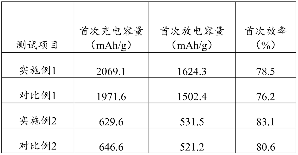
Embodiment 1
[0043] This embodiment is a carbon coating method of silicon oxide, comprising the following steps:
[0044] Step s1: Weigh 10g of SiO 2 Put it into the rotary furnace, pass in argon protective gas, raise the temperature of the rotary furnace to 1200 °C at a rate of 5 °C / min; turn on the rotation of the rotary furnace, set the speed at 10 r / min, close the argon valve, and turn on the carbon source gas Valve, so that ethylene gas enters the rotary furnace at a flow rate of 0.1L / min, and reacts for 30 minutes to end the reaction; close the carbon source gas valve, open the argon valve, and take out the material after the argon gas protection drops to room temperature to obtain SiO 2 / C1 composite material;
[0045] Step s2: Weigh 2g sucrose and 3.4g SiO 2 / C1 composite material, first dissolve sucrose in 20ml ethanol solvent to form a homogeneous solution, then add SiO to the solution 2 / C1 composite material, fully stirred to form a dispersion;
[0046] Step s3: Heat the di...
Embodiment 2
[0053] This embodiment is a carbon coating method of SnO, comprising the following steps:
[0054] Step s1: Weigh 10g of SnO into the rotary furnace, pass in argon protective gas, and raise the temperature of the rotary furnace to 1200°C at a rate of 5°C / min; turn on the rotation of the rotary furnace, and set the speed to 10r / min, Close the argon gas valve, open the carbon source gas valve, let ethane enter the rotary furnace at a flow rate of 0.1L / min, and react for 30 minutes to end the reaction; close the carbon source gas valve, open the argon gas valve, and after the argon protection drops to room temperature, Take out the material to obtain the SnO / C1 composite material;
[0055] Step s2: Weighing 2g of glucose and 3.6g of SnO / C1 composite material, first dissolving the glucose in 20ml of ethanol solvent to form a homogeneous solution, then adding the SnO / C1 composite material into the solution, and fully stirring to form a dispersion;
[0056] Step s3: heat the disper...
Embodiment 3
[0064] This embodiment is a carbon coating method for silicon, comprising the following steps:
[0065] Step s1: Weigh 10g of Si and put it into the rotary furnace, pass in argon, raise the temperature of the rotary furnace to 1200°C at a rate of 5°C / min; turn on the rotation of the rotary furnace, set the speed to 10r / min, and turn off the argon Valve, open the carbon source gas valve, let ethylene gas enter the rotary furnace at a flow rate of 0.1L / min, and react for 20 minutes to end the reaction; close the carbon source gas valve, open the argon valve, and take out the material after the argon protection drops to room temperature to obtain Si / C1 composite material;
[0066] Step s2: Weighing 2g of glucose and 3.6g of Si / C1 composite material, first dissolving glucose in 20ml of ethanol solvent to form a homogeneous solution, then adding Si / C1 composite material into the solution, and fully stirring to form a dispersion;
[0067] Step s3: heat the dispersion liquid, and af...
PUM
 Abstract
Description
Claims
Application Information
 - R&D
- Intellectual Property
- Life Sciences
- Materials
- Tech Scout
- Unparalleled Data Quality
- Higher Quality Content
- 60% Fewer Hallucinations
Browse by: Latest US Patents, China's latest patents, Technical Efficacy Thesaurus, Application Domain, Technology Topic, Popular Technical Reports.
© 2025 PatSnap. All rights reserved.Legal|Privacy policy|Modern Slavery Act Transparency Statement|Sitemap|About US| Contact US: help@patsnap.com


