Constant-force grinding device and grinding control method thereof

A technology of a grinding device and a control method, which is applied in the direction of a grinding device, a grinding automatic control device, program control, etc., can solve problems such as uncontrollable grinding force, and achieve the effect of improving the grinding quality and changing the grinding force smoothly

Pending Publication Date: 2019-01-15
SOUTH CHINA UNIV OF TECH
View PDF0 Cites 12 Cited by
  • Summary
  • Abstract
  • Description
  • Claims
  • Application Information

AI Technical Summary

Problems solved by technology

The grinding device of the present invention can solve the problem that the grinding force is uncontrollable in the grinding process of the existing robot. Through the cooperatio

Method used


Image

  • Constant-force grinding device and grinding control method thereof
  • Constant-force grinding device and grinding control method thereof
  • Constant-force grinding device and grinding control method thereof

Examples


Embodiment 1

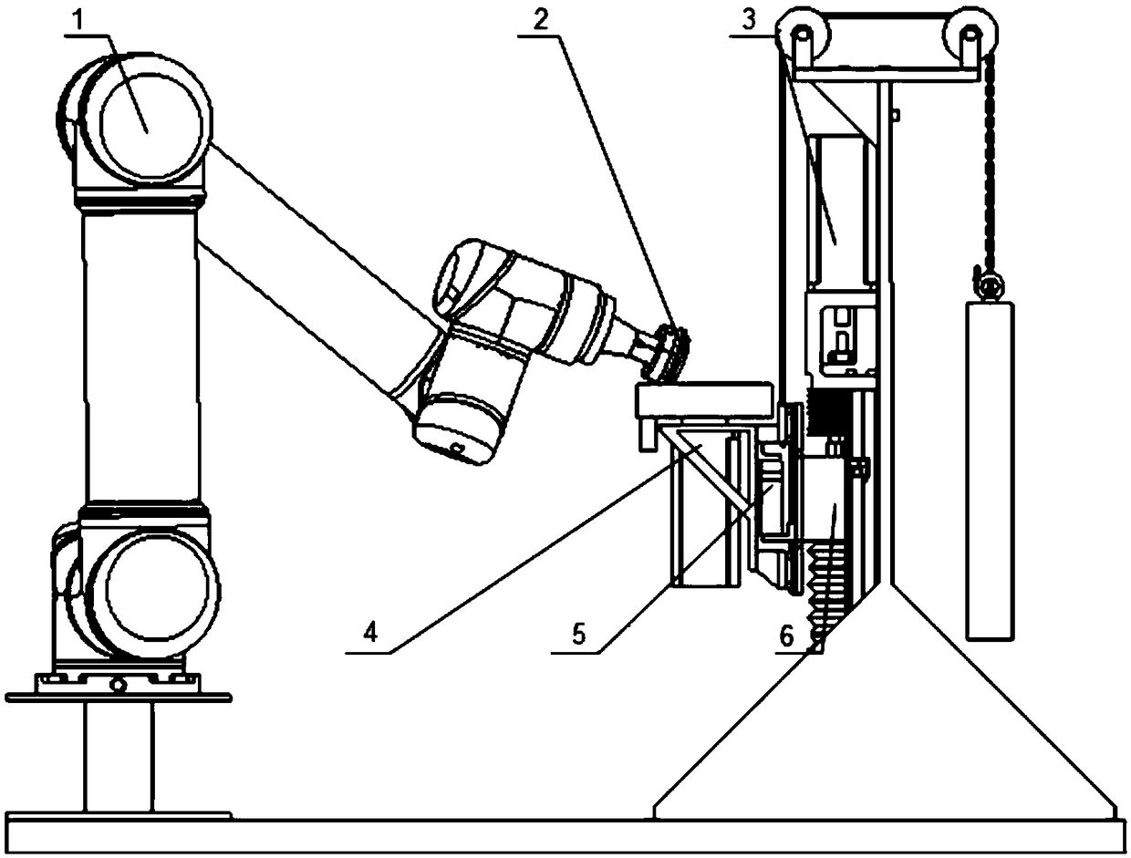
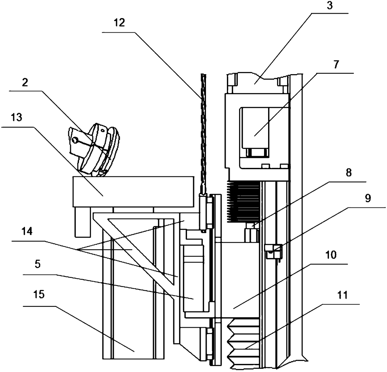
[0067] Such as Figure 1-2 As shown, a constant force grinding device includes a six-degree-of-freedom industrial robot 1, a floating grinder, a one-dimensional force sensor 5, a data acquisition device, a constant force device and a controller;

[0068] The floating grinding table on the floating grinding machine rotates at a constant speed, the end of the six-degree-of-freedom industrial robot clamps the workpiece 2 to be ground, and the workpiece to be ground is ground on the grinding sand table 13 of the floating grinding table 4; a one-dimensional force sensor is installed on the lower side of the floating grinding machine , the one-dimensional force sensor is connected to the controller through a data acquisition device, the constant force device includes an AC servo motor 3 and a linear motion module 6, and the linear motion module is driven by the AC servo motor 3 to adjust the workpiece to be ground and the floating grinding table The relative position of the AC servo...

Embodiment 2

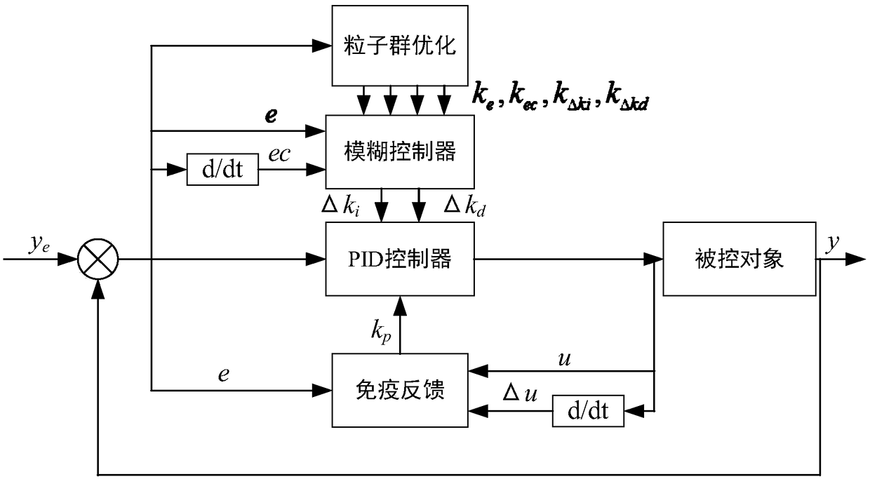
[0074] Such as figure 2 Shown, a kind of grinding control method based on the constant force grinding device of embodiment 1 comprises the following steps:

[0075] S1. Control the workpiece to be ground at the end of the industrial robot to enter the floating grinding table for grinding according to the pre-track;

[0076] S2. The one-dimensional force sensor obtains the grinding force analog signal;

[0077] S3. Calculate the grinding force error and the error change value according to the currently collected grinding force analog signal and the expected value, and use it as the input of the adaptive PID controller;

[0078] S4. The output of the adaptive PID controller is the control quantity of the AC servo motor. The AC servo motor drives the linear motion module to adjust the relative position of the workpiece to be ground and the floating grinding table in real time according to the above control quantity, thereby controlling the grinding force.

[0079] The processa...


PUM


Abstract

The invention discloses a constant-force grinding device. The device comprises a six-degree-of-freedom industrial robot, a floating grinder, a first-dimensional force sensor, a data acquiring device,a constant-force device and a controller. The invention also discloses a grinding control method on the basis of the abovementioned constant-force grinding device. The method comprises the following steps: grinding a workpiece to be grinded to grind based on a preset track; acquiring a grinding force simulating signal by the first-dimensional force sensor; calculating the grinding force error andthe error variation value based on the grinding force simulating signal and an expected value, and treating the grinding force error and the error variation value as input of a self-adaptive PID controller, wherein the output of the self-adaptive PID controller is the controlled variable of a servo motor; driving a linear movement die set to adjust in real time based on the controlled variable, and thus controlling the grinding force. With the adoption of the device, intelligent constant-force control is realized; the polishing and grinding production rate is increased; the product consistencyis ensured; the working conditions of workers are improved; and the cost is saved.

Description

technical field [0001] The invention relates to the field of robot constant force grinding control engineering, in particular to a robot constant force grinding device based on a floating table and a grinding control method thereof. Background technique [0002] Polishing and grinding is the most basic process of mechanical processing, and its cost accounts for 30% of the total cost. Generally, industrial grinding and polishing operations are completed manually, which is labor-intensive, low-efficiency, and the working environment is extremely poor. With the disappearance of the demographic dividend, the reduction of product costs and the requirements for improved product quality, the market demand for grinding and polishing robots is becoming stronger and stronger. The use of grinding and polishing robots has a good effect on improving the grinding quality and product finish, ensuring its consistency, increasing productivity, and improving workers' working conditions. [...

Claims


Application Information

Patent Timeline
IPC IPC(8): B24B37/005B24B49/16B24B51/00G05B19/414
CPCG05B19/4142B24B37/005B24B49/165B24B51/00G05B2219/34013
Inventor 张铁蔡超吴圣和
Owner SOUTH CHINA UNIV OF TECH
Why Eureka
Try Eureka