Power plant waste heat and clean energy comprehensive utilization system

A technology of clean energy and power plant waste heat, applied in heating systems, space heating and ventilation, applications, etc., can solve the problem of low circulating water temperature, failure to meet the grade requirements of direct heating, and insufficient exhaust heat of low-pressure cylinders Use and other issues to achieve the effect of reducing the heat loss of the flue gas, reducing the heat loss of the cold source, and improving the thermal efficiency of energy

Pending Publication Date: 2019-01-15
CHONGQING CISDI THERMAL & ENVIRONMENTAL ENG CO LTD
View PDF7 Cites 3 Cited by
  • Summary
  • Abstract
  • Description
  • Claims
  • Application Information

AI Technical Summary

Problems solved by technology

However, the large amount of waste heat generated by the large-capacity and high-parameter generator sets has not been fully utilized at present
[0004] The problem existing in the utilization of waste heat of circulating water in power plants is that the temperature of circulating water is usually relatively low, which cannot meet the grade requirements for direct heating. It is necessary to try to increase the temperature appropriately. There are two methods that can be used: one is to reduce the vacuum of the exhaust cylinder and increase the exhaust gas. steam temperature, which is commonly referred to as the low-vacuum operation of the steam turbine unit; the second is to use the circulating water of the power plant as a low-level heat source, and use heat pump technology to absorb the waste heat to achieve heat supply

Method used


Image

  • Power plant waste heat and clean energy comprehensive utilization system

Examples


Embodiment Construction

[0022] The preferred embodiments of the present invention will be described in detail below with reference to the accompanying drawings.

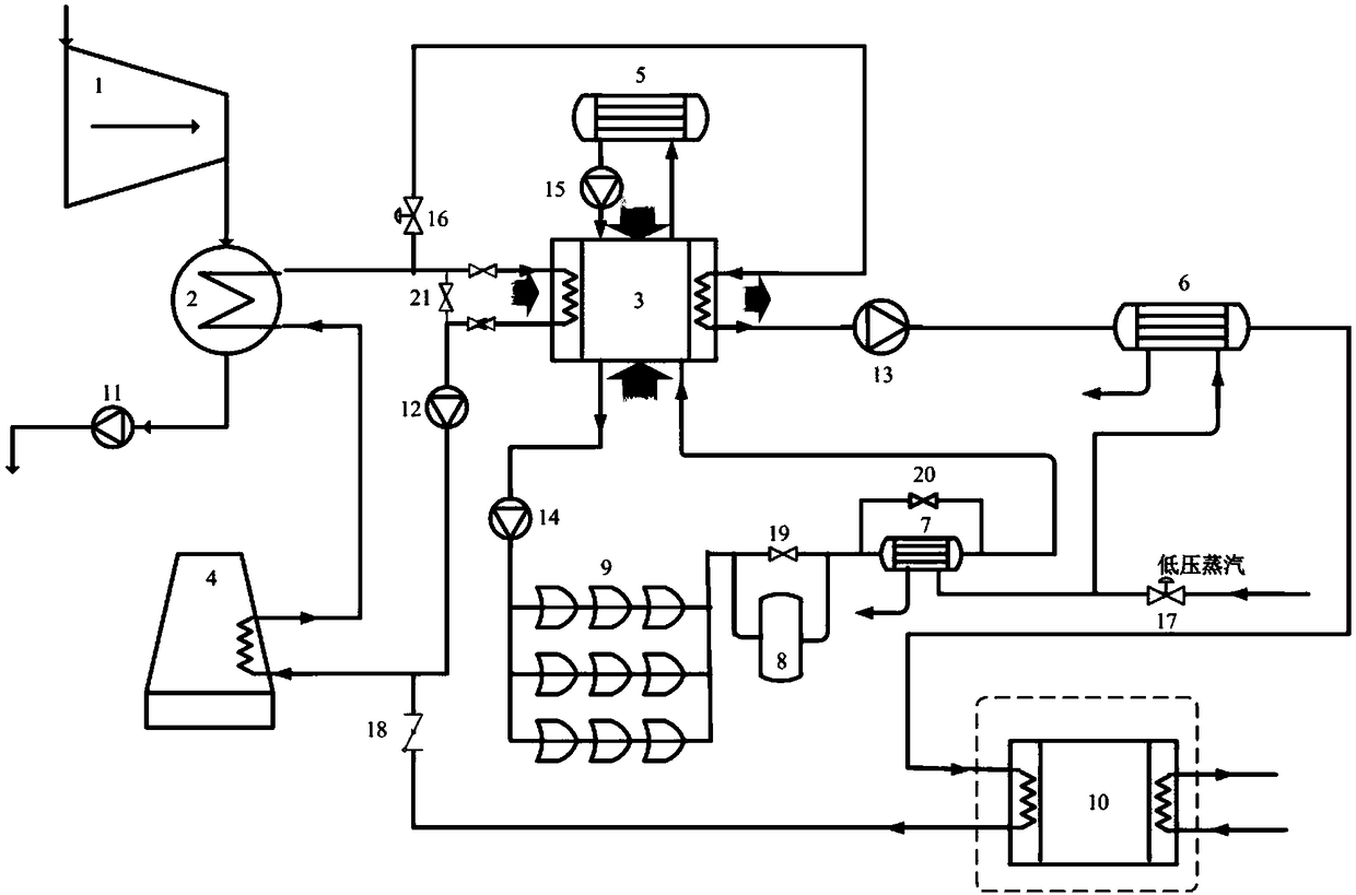
[0023] figure 1 It is a schematic diagram of the system of circulating water waste heat recovery, flue gas waste heat recovery and solar heat collection recovery of intermediate indirect air-cooled units. The indirect cooling surface condenser system is a Harmon system. see figure 1 , the circulating cooling water waste heat recovery, flue gas waste heat recovery and solar heat collection recovery system in this embodiment include a steam turbine unit 1, a condenser 2, an absorption heat pump 3, an indirect air cooling tower 4, and a flue gas-water heat exchanger 5. Steam-water heat exchanger 6, steam-heat transfer oil heat exchanger 7, heat accumulator 8, trough solar collector 9, secondary network heat exchange station 10, condensate pump 11, circulating water pump 12, hot water Circulation pump 13, heat conduction oil circulation pump ...


PUM


Abstract

The invention relates to a power plant waste heat and clean energy comprehensive utilization system, and belongs to the technical field of energy utilization. The system comprises a steam turbine unit, a condenser, an absorption heat pump, an indirect air cooling tower, a flue gas-water heat exchanger, a steam-water heat exchanger, a steam-conduction oil heat exchanger, a heat accumulator, a groove type solar heat collector, a secondary network heat exchange station, a circulating water pump, a hot water circulating pump I, a heat conduction oil circulating pump, a hot water circulating pump II, a circulating water regulating valve and a check valve. By means of the heat pump technology, power plant circulating water serves as a low-level heat source, the flue gas and the solar energy serve as driving energy sources to supply heating water at the temperature of 75 DEG C to the outside, and if necessary, the water is subjected to the secondary heating to be heated to 110 DEG C and fed into an urban heat network. According to the invention, the heat loss of the cold source of the steam turbine is reduced, the heat loss of the flue gas is reduced, and a solar energy collecting systemis arranged on the plane of the power plant, the solar energy is effectively utilized, the comprehensive energy utilization system of the power plant is formed, and the energy heat efficiency of the power plant is improved.

Description

technical field [0001] The invention belongs to the technical field of energy utilization, and relates to a comprehensive utilization system of waste heat and clean energy of a power plant. Background technique [0002] In the environmental pollution control of power plants, we have always paid great attention to the dust removal and desulfurization of power plant flue gas, the clean treatment of coal combustion, and strict control of nuclide pollution standards, so as to have a negative thermal impact on the possible negative thermal impact of the huge heat contained in circulating cooling water being discarded to the environment. , and even the harm of thermal pollution is easily overlooked. [0003] With the rapid expansion of urban scale, the problem of insufficient centralized heat sources has appeared in many places in my country, and the problems of urban environment and economic carrying capacity caused by heating have become increasingly prominent. However, the lar...

Claims


Application Information

Patent Timeline
Patent Type & Authority Applications(China)
IPC IPC(8): F28D7/16F24D15/02F24D15/04
CPCF24D15/02F24D15/04F28D7/16
Inventor 王方明李斌王毅杜文亚张茂谭智海
Owner CHONGQING CISDI THERMAL & ENVIRONMENTAL ENG CO LTD
Why Eureka
Try Eureka