Non-reciprocal phase shift device-based Sagnac interference type high-current optical fiber current transformer measurement method

A non-reciprocal phase-shift and fiber-optic current technology, applied in the direction of measuring devices, measuring electrical variables, instruments, etc., can solve problems such as difficult access to optical fibers and difficulties in commodity operation, achieve good system polarization, reduce modulation circuits and algorithms, and improve Effect of System Accuracy

Active Publication Date: 2019-01-15
STATE GRID JIBEI ELECTRIC POWER CO LTD TANGSHAN POWER SUPPLY CO +1
View PDF13 Cites 2 Cited by
  • Summary
  • Abstract
  • Description
  • Claims
  • Application Information

AI Technical Summary

Problems solved by technology

[0005] The optical fiber current sensor has a simple structure and low cost, but it is difficult to obtain the optical fiber that can maintain the circular

Method used


Image

  • Non-reciprocal phase shift device-based Sagnac interference type high-current optical fiber current transformer measurement method
  • Non-reciprocal phase shift device-based Sagnac interference type high-current optical fiber current transformer measurement method
  • Non-reciprocal phase shift device-based Sagnac interference type high-current optical fiber current transformer measurement method

Examples


Embodiment Construction

[0015] The present invention will be further described through the embodiments below in conjunction with the accompanying drawings. Apparently, the described embodiments are only some of the embodiments of the present invention, but not all of them. Based on the embodiments of the present invention, all other embodiments obtained by persons of ordinary skill in the art without making creative efforts belong to the protection scope of the present invention.

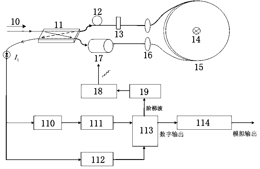
[0016] A method for measuring a Sagnac interferometric high-current fiber optic current transformer based on a non-reciprocal phase-shift device, comprising the following steps: (1) building a non-reciprocal phase shifter, using a circularly polarized optical fiber to make a current sensing head, and an optical fiber ring The number of turns is calculated from the relationship formula between the magnetic rotation angle of the annular Sagnac current transformer and the minimum detection range of the measured current, and a...


PUM


Abstract

The invention relates to a non-reciprocal phase shift device-based Sagnac interference type high-current optical fiber current transformer measurement method, and belongs to the technical field of electric measurement. The method comprises the following steps of: (1) constructing a non-reciprocal phase shift device, manufacturing a current sensing head by adoption of a circularly polarized fiber,fixedly arranging a phase modulator at one end of an Sagnac delay coil, and importing a Pi/2 non-reciprocal phase deviation; (2) carrying out phase detection, and demodulating a circuit by using a phase discrimination manner so as to finally realize a phase demodulation manner unrelated to light intensity; (3) obtaining an output waveform oscillogram and precision of the current by utilizing a Faradic current sensing experiment; and (4) controlling phase interference caused by slow variables such as temperature and light source intensity changes through applying voltages with different frequencies on an electro-optical crystal, so as to improve the phase precision. According to the method, linear birefringence caused by long delay coils is decreased, the system polarization is better kept,the system precision is improved, a modulation circuit and an algorithm required by a phase deviator are decreased, and the sensor reaction time is prolonged.

Description

technical field [0001] The invention relates to a method for measuring a Sagnac interference type high-current optical fiber current transformer based on a non-reciprocal phase-shifting device, and belongs to the technical field of electrical measurement. Background technique [0002] Today, as people are stepping into the modern society, the power transmission capacity is increasing, and the transmission voltage is getting larger and larger. We need to face the problem of accurate measurement of large currents, the electrical insulation between instruments and the reliability requirements of signal transmission. May render traditional means of measurement powerless. For electric energy systems with high voltage, high current and high power, the current intensity measurement technology based on electromagnetic induction has exposed a series of shortcomings, such as poor insulation, high cost, heavy weight, large volume, magnetic saturation, and small dynamic range. , Narrow...

Claims


Application Information

Patent Timeline
IPC IPC(8): G01R35/02
CPCG01R35/02
Inventor 董悦坤夏嘉明
Owner STATE GRID JIBEI ELECTRIC POWER CO LTD TANGSHAN POWER SUPPLY CO
Why Eureka
Try Eureka