A distribution transformer fuel tank suitable for welding robot operation and its design and processing method

A technology for welding robots and fuel tanks, applied in the manufacture of inductors/transformers/magnets, electrical components, circuits, etc., can solve the problem of poor aesthetics of factory transformers and station transformers, and the accuracy of human control is accurate to within two decimal places. Problems such as low production efficiency, achieve reasonable production accuracy and aesthetics, facilitate standardized work, and improve production efficiency.

Active Publication Date: 2020-11-20
山东泰开箱变有限公司
View PDF6 Cites 0 Cited by
  • Summary
  • Abstract
  • Description
  • Claims
  • Application Information

AI Technical Summary

Problems solved by technology

After these processes are completed, the deep processing of the box edge is considered to be completed, and other situations (such as machine fatigue and wear, human error, etc.) are not considered in the middle. It takes about 8 to 9 scattered processes to complete, and a skilled worker takes about 10 to 15 minutes to complete each small process on average. In addition to the time for material transfer and transportation in the middle, there is a total waste of nearly 2 hours In the processing of the edge of the box, this is why many factories have a large number of workers and work overtime, but the root cause of the problem is that the efficiency has not been improved. The main disadvantages are cumbersome procedures, long process time, and too much waste of manpower and material resources. too serious
[0005] 3. Combination welding and full welding are carried out on the deep-processed materials. The shortcomings and problems of this step of processing are more prominent, mainly in the processing accuracy and error. Traditional manual welding cannot achieve artificial control accuracy to within two decimal places. , is often close to the limit at 0.1-0.5mm, although it will not have a great impact on the use of the actual transformer oil tank, but for equipment such as sets and combined box transformers that require precise coordination, it is already an obvious aspect of coordination the problem
In addition, the appearance of conventional hand-welded fuel tanks often has very thick and obvious welds or even weld spots, which has a very bad impact on the aesthetics of independently used factory transformers and station transformers.
[0006] To sum up, from blanking, cutting, bending, assembly welding, full welding to the final pickling and phosphating painting, a lot of manpower and material resources are required, the production efficiency is low, the waste of materials is serious, and the quality of finished products is uneven. Yield rate bottom
[0007] In recent years, some manufacturers have begun to use robot welding to replace manual welding. However, because the fuel tank welding robot technology is not yet mature, it is impossible to propose effective solutions for the traditional fuel tank structure and welding mode. Now, traditional manual welding is basically used. The fuel tank structure designed in the welding mode makes it difficult for many robot manufacturers to provide a standardized tooling solution, and the general operation of temporarily changed tooling is also frequently hindered, and the robot's welding ability cannot be fully utilized. The actual effect is very small, so that the transformer manufacturers cannot realize the initial expected production capacity increase and product upgrade.

Method used


Image

  • A distribution transformer fuel tank suitable for welding robot operation and its design and processing method
  • A distribution transformer fuel tank suitable for welding robot operation and its design and processing method
  • A distribution transformer fuel tank suitable for welding robot operation and its design and processing method

Examples


Embodiment Construction

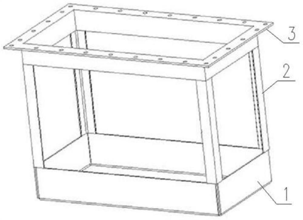
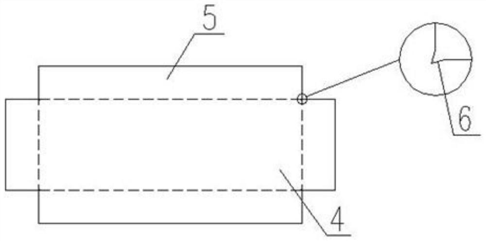
[0034] Attached below Figure 1-3 The specific method of the present invention and the manufacturing scheme of the robot welding are further described.

[0035] The traditional hand-welded fuel tank does not have the so-called skeleton structure, but simply uses the outer side walls of four angle steels to weld the box edge and the inner wall of the box bottom together, and then use the transformer's heat sink (corrugated wall) to connect the box edge and the outer side of the bottom of the box. Wrap welding. This traditional welding method is obviously not suitable for robot welding operations, because the robot welding needs to be supported by an inner support tool that can rotate freely in a plane, and then the robot welding torch is welded along a fixed route from the outside to complete the work. , the design scheme of the traditional hand-welded fuel tank adopts the internal welding mode in terms of the fixed edge and bottom of the tank (that is, the welding of the four...


PUM

PropertyMeasurementUnit
thicknessaaaaaaaaaa

Abstract

The invention provides a transformer oil tank adapted to welding robot and a design and processing method thereof. The three-layer skeleton with distinct hierarchy comprises a bottom part connected from bottom to top in turn, a main body skeleton part and a box edge part. The semi-finished product of the oil tank is welded on the outside, so that the welding gun of the manipulator is convenient towork. The panel at the bottom of the transformer is designed by integrative molding, the right angle of the bottom of the transformer is slotted by triangle method, and the main body skeleton is positioned by groove method. Through the design method and the structural design of the oil tank skeleton, a standard process flow is provided to the transformer manufacturer, and the production efficiency of the transformer manufacturer is improved. It solves the problem that welding torch is difficult to enter when welding robot on traditional oil tank is working, and solves the problem that weldingtorch is difficult to enter when welding robot is working. Convenient for welding robot manufacturers to uniformly plan the standardization of various types of supporting tooling; Reduce production costs, reasonable control of the production accuracy and aesthetics of products.

Description

technical field [0001] The invention relates to the field of distribution transformer oil tank equipment, in particular to a distribution transformer fuel tank suitable for welding robot operations and a design and processing method thereof. Background technique [0002] At present, the production of domestic distribution transformer fuel tanks mainly relies on manpower. The usual process of traditional manual welding of fuel tanks includes the following steps: [0003] 1. The workshop blanks the main steel plates and structural parts (angle steel, channel steel, steel pipe, etc.) according to the drawings. The steel plate mainly depends on the copy cutting machine or the plasma flame cutting machine. We use the plasma flame cutting machine to process the box cover. Taking steel plate as an example, the diameter of the flame nozzle for conventional plasma flame cutting is between 8 and 15 mm. In this case, the flame cutting strength can burn through the original plate (inclu...

Claims


Application Information

Patent Timeline
Patent Type & Authority Patents(China)
IPC IPC(8): H01F41/00
CPCH01F41/00
Inventor 苏中信刘建萍朱宏马少永汪远文张安军
Owner 山东泰开箱变有限公司
Why Eureka
Try Eureka