Hollow fiber membrane oxygenator externally arranged on heat exchange layer

A technology of heat exchange layer and oxygenator, which is applied in the field of medical devices, can solve the problems of reduced blood flow uniformity, reduced thrombus formation, and reduced gas exchange efficiency, so as to reduce the probability of thrombus formation, small body temperature fluctuations, and temperature loss low effect

Inactive Publication Date: 2019-01-18
GUANGDONG UNIV OF TECH
View PDF9 Cites 17 Cited by
  • Summary
  • Abstract
  • Description
  • Claims
  • Application Information

AI Technical Summary

Problems solved by technology

[0005] The technical problem to be solved by the present invention is to overcome the deficiencies of the above-mentioned prior art, provide a hollow fiber membrane oxygenator with an external he...

Method used


Image

  • Hollow fiber membrane oxygenator externally arranged on heat exchange layer
  • Hollow fiber membrane oxygenator externally arranged on heat exchange layer
  • Hollow fiber membrane oxygenator externally arranged on heat exchange layer

Examples


Embodiment 1

[0044] Example 1 A hollow fiber membrane oxygenator with an external heat exchange layer

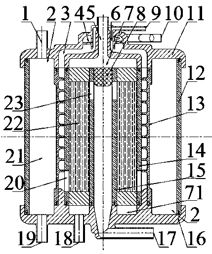
[0045] A hollow fiber membrane oxygenator with an external heat exchange layer, such as figure 1 As shown, the overall shape is cylindrical; the oxygenator includes a shell and an upper end cover 11 and a lower end cover 16 detachably installed on the shell; the shell includes an oxygenator shell 12, a hot water unit Shell 13, oxygenation unit shell 14 and core tube 15; the oxygenator shell 12 and the hot water unit inner shell 13 form the cavity of the hot water unit 21, and the hot water unit inner shell 13 and the oxygenation unit shell 14 form the blood heat exchange Cavity, the shell 14 of the oxygenation unit and the core tube 15 constitute the cavity of the oxygenation unit 22 (that is, the oxygen-permeable hollow fiber membrane).

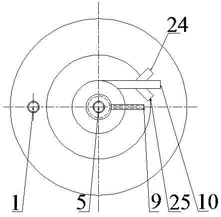
[0046] Such as figure 2 As shown, the upper end cover 11 is respectively provided with a water outlet pipe 1, an air inlet pipe 5, an exhaust pipe ...

Embodiment 2

[0062] Example 2 A hollow fiber membrane oxygenator with an external heat exchange layer

[0063] In order to further improve the comprehensive use effect of the oxygenator, the hollow fiber membrane oxygenator with an external heat exchange layer in this embodiment has the following improvements on the basis of Example 1:

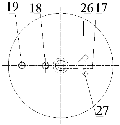
[0064] Such as figure 1 , Figure 5 and Image 6 As shown, in the hollow fiber membrane oxygenator with an external heat exchange layer in this embodiment, the four first circumferential openings 20 at the lower end of the oxygenation unit housing 14 and the four second circumferential openings at the upper end of the core tube 15 The outer edges of 23 are rounded. The rounded corner design can fully reduce the shearing effect between the blood and the edge of the hole when the blood flows through the hole, and reduce the degree of blood damage. A seal 8 with rounded corners is provided on the upper part of the inner cavity of the core tube 15 . When ...


PUM


Abstract

The invention discloses a hollow fiber membrane oxygenator which is externally arranged on a heat exchange layer. The oxygenator comprises a housing and an upper end cover and a lower end cover detachably mounted on the housing. The housing includes an oxygenator housing, a hot water unit inner housing, an oxygenation unit housing and a core tube from the outside to the inside. The oxygenator shell and the hot water unit shell form a cavity of the hot water unit, the hot water unit shell and the oxygenation unit shell form a blood heat exchange cavity, and the oxygenation unit shell and the core pipe form a cavity of the oxygenation unit; The blood heat exchange chamber is communicated with the oxygenation unit through a circumferential opening. The hot water unit of the invention is arranged at the periphery of the oxygenation unit, so that not only the gas exchange efficiency can be improved, but also the temperature loss can be minimized to achieve the highest oxygenation efficiency. In addition, the temperature gradient of the oxygenator is very small, which can significantly reduce the probability of thrombosis in blood. At the same time, the blood temperature after oxygenation is close to the internal temperature of human body, which can bring better treatment experience.

Description

technical field [0001] The invention belongs to the technical field of medical equipment. More specifically, it relates to a hollow fiber membrane oxygenator with an external heat exchange layer. Background technique [0002] In the clinical medical process of cardiopulmonary surgery, the core component of extracorporeal circulation, namely the oxygenator, has always played an important role. Membrane oxygenator, also known as "artificial lung", is used for extracorporeal circulation of blood in open heart surgery, so that human blood can exchange oxygen and carbon dioxide outside the body, that is, the "oxygenation" function. Therefore, the membrane oxygenator belongs to the biomedical engineering industry, is the core component of the extracorporeal membrane oxygenation system of life support equipment, and is a key product of strategic emerging industries. [0003] The oxygenators commonly used in the market now mainly have two functions, namely heat exchange (hot water...

Claims


Application Information

Patent Timeline
IPC IPC(8): A61M1/36A61M1/18
CPCA61M1/1623A61M1/1698A61M1/3621A61M1/3666A61M2202/0413A61M2202/0021
Inventor 叶非华易国斌余振东
Owner GUANGDONG UNIV OF TECH
Why Eureka
Try Eureka