Rotary flow field type continuous mixing equipment for ceramic powder

A technology of ceramic powder and mixing equipment, which is applied in mixers with rotating containers, mixers, dissolving and other directions, can solve the problems of time-consuming, affecting the quality of the working environment, uneven mixing, etc., and achieves a reduction in powder dispersion. Possibilities, compact machine design, improved mixing uniformity

Inactive Publication Date: 2019-01-18
JINGDEZHEN CERAMIC INSTITUTE
View PDF8 Cites 2 Cited by
  • Summary
  • Abstract
  • Description
  • Claims
  • Application Information

AI Technical Summary

Problems solved by technology

The disadvantage of traditional vertical ceramic powder mixing equipment is that there are the following main problems: ① Uneven mixing: when various ceramic powders are placed in the cylinder of the traditional vertical ceramic powder mixing machine, due to stirring Due to the limitations of the blades of the mechanism, there is a material dead angle at the bottom, and it is impossible to effectively mix various ceramic powders evenly, which leads to a series of defects in the produced ceramic products; ②Low efficiency: traditional vertical ceramic powder The mixing machine is an intermittent mixing e

Method used


Image

  • Rotary flow field type continuous mixing equipment for ceramic powder
  • Rotary flow field type continuous mixing equipment for ceramic powder
  • Rotary flow field type continuous mixing equipment for ceramic powder

Examples


Embodiment 1

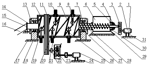
[0030] see figure 1 , in an embodiment of the present invention, a ceramic powder rotary flow field continuous mixing equipment, including a support foot 1, a first motor 2, a reducer 3, the first motor 2 is arranged on the support foot 1, and the support foot The role of 1 in this system is to play a supporting role for the first motor 2, preventing the first motor 2 from unnecessary damage when it is placed directly on the ground; there is a storage tank on the left side of the first motor 2 6. A spiral reamer 7 is arranged in the storage barrel 6, and the output shaft of the first motor 2 is connected to the right end of the spiral reamer 7 through a reducer 3. The function of the storage barrel 6 in this system is to temporarily store various Ceramic powder and regulator, waiting for the spiral reamer 7 to transport the material into the mixing cylinder 12; The various ceramic powders and regulators are transported to the inside of the mixing cylinder 12 together;

Embodiment 2

[0032] see figure 1 with Figure 7 The left side of the storage barrel 6 is provided with two bases 18, the base 18 is respectively connected with the left hollow shaft 14 and the right hollow shaft 28 through the second bearing 27, and the left hollow shaft 14 and the right hollow shaft 28 are jointly fixed The mixing cylinder 12 is connected, and the function of the left hollow shaft 14 is to carry out fixed connection processing with the left side of the mixing cylinder 12, together with the right hollow shaft 28 under the radial fixation of the second bearing 27, to support the mixing cylinder body 12 in rapid rotation, while the left hollow shaft 14 outputs the uniformly mixed material inside the mixing cylinder 12 into the corresponding collection device; the outside of the mixing cylinder 12 is connected with a belt transmission mechanism 11, and the belt transmission mechanism 11 passes The coupling 22 is connected with a transmission 23, and the transmission 23 is co...

Embodiment 3

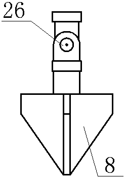
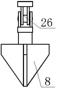
[0034] see figure 1 , figure 2 , image 3 with Figure 4 A plurality of second motors 10 are evenly arranged on the outer wall of the mixing cylinder 12, the output shafts of the second motors 10 extend to the inside of the mixing cylinder 12, and the output shafts of the second motors 10 are hinged by living hinges 26 There is a stirring knife 8, and the stirring knife 8 stirs and disperses various ceramic powders inside the mixing cylinder 12, so that the powders form an irregular floating state, and then promotes the separation of various ceramic powders by continuously stirring the powders. Interpenetration and mixing between them; the function of the living hinge 26 in the present invention is to transfer the kinetic energy of the second motor 10 to the stirring cutter 8, so that the stirring cutter 8 can stir various ceramic powders in the mixing cylinder 12 Scattering promotes the mixing uniformity of materials; at the same time, the living hinge 26 can expand the f...


PUM


Abstract

The invention relates to the technical field of ceramic powder mixing machines and in particular relates to rotary flow field type continuous mixing equipment for ceramic powder. The rotary flow fieldtype continuous mixing equipment comprises a supporting leg, a first motor and a speed reducer, wherein the first motor is arranged on the supporting leg; a material storage barrel is arranged at theleft side of the first motor; a spiral reamer is arranged in the material storage barrel; an output shaft of the first motor is connected with the right end of the spiral reamer through the speed reducer; two bases are arranged at the left side of the material storage barrel; the bases are provided with a left hollow rotary shaft and a right hollow rotary shaft respectively through second bearings. The rotary flow field type continuous mixing equipment for the ceramic powder has the beneficial effects that materials are uniformly mixed, and all the raw materials are subjected to a centrifugalforce due to rapid rotation so that a dead angle problem of the materials is not caused; when the materials fall off from the topmost part of an inner wall of a mixing barrel body and are scattered,a stirring tool which is rotated rapidly has a stirring and shearing force effect; the materials are irregular dispersed and are mixed; the mixing uniformity of the ceramic powder is improved due to random mixing.

Description

technical field [0001] The invention relates to the technical field of ceramic powder mixers, in particular to a ceramic powder rotating flow field continuous mixing equipment. Background technique [0002] Ceramic powder mixer is the key equipment for ceramic production enterprises to produce ceramic products. It has an increasingly important influence on the quality of ceramic products and is an indispensable part of modern ceramic production. The disadvantage of traditional vertical ceramic powder mixing equipment is that there are the following main problems: ① Uneven mixing: when various ceramic powders are placed in the cylinder of the traditional vertical ceramic powder mixing machine, due to stirring Due to the limitations of the blades of the mechanism, there is a material dead angle at the bottom, and it is impossible to effectively mix various ceramic powders evenly, which leads to a series of defects in the produced ceramic products; ②Low efficiency: traditional ...

Claims


Application Information

Patent Timeline
IPC IPC(8): B01F9/08B01F9/06B01F15/02B01F29/64B01F29/63
CPCB01F29/15B01F29/251B01F29/63B01F29/64B01F35/71775
Inventor 余冬玲宁翔冼倍林吴南星江竹亭廖达海
Owner JINGDEZHEN CERAMIC INSTITUTE
Why Eureka
Try Eureka