Rotary forging die clamp and surface processing method thereof

A rotary forging and surface treatment technology, which is applied in the field of forging mold fixtures, can solve the problems of inability to clamp non-traditional square molds, deviate from the original requirements of processing molds, and the cumbersome process of centering and leveling, etc., to achieve surface and internal Effects of improved mechanical properties, increased efficiency, and easy control

Inactive Publication Date: 2019-01-18
ZHEJIANG YUEJIN MACHINERY
View PDF7 Cites 1 Cited by
  • Summary
  • Abstract
  • Description
  • Claims
  • Application Information

AI Technical Summary

Problems solved by technology

[0005] In order to solve the problem that the existing fixture cannot effectively and stably clamp the non-traditional square mold, it is difficult to fix and clamp, reduce production efficiency, and it causes uneven force on the mold, and it is easy to cause the workpiece to shake during production and processing, resulting in The processing mold deviates from the original requirements, and the process of centering and leveling by the operator is very cumbersome and cannot guarantee the quality. Unconventional square mold for stable and effective clamping

Method used


Image

  • Rotary forging die clamp and surface processing method thereof

Examples


Embodiment 1

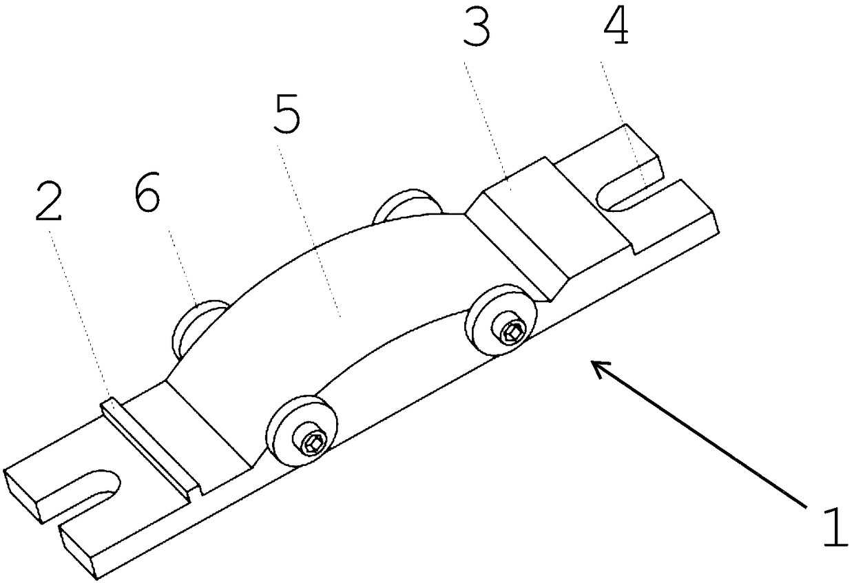
[0036] Such as figure 1 As shown in a rotary forging die fixture, the base body 1 is a cuboid, and a fixing slot 4 is provided at both ends of the long direction, which is used for fixing the processing machine tool. An arch bridge base 5 is provided on one side of the cuboid. The arch bridge base 5 fits the arc surface of the rotary forging die, and the fastening devices 6 on both sides of the arch bridge base 5 lock and fix the rotary forging die, which greatly improves the traditional furniture that cannot effectively and stably fix the rotary forging die. The disadvantage is that a positioning slope 3 and a positioning block 2 are oppositely provided at both ends of the arch bridge base 5 along the long direction of the main body 1, which can realize the rapid positioning of the rotary forging die and improve the processing efficiency.

[0037] The carburizing medium used in this example is SiC as carbon source with BaCO 3 As a solid carburizing medium composed of an infi...

Embodiment 2

[0039] Such as figure 1As shown in a rotary forging die fixture, the base body 1 is a cuboid, and a fixing slot 4 is provided at both ends of the long direction, which is used for fixing the processing machine tool. An arch bridge base 5 is provided on one side of the cuboid. The arch bridge base 5 fits the arc surface of the rotary forging die, and the fastening devices 6 on both sides of the arch bridge base 5 lock and fix the rotary forging die, which greatly improves the traditional furniture that cannot effectively and stably fix the rotary forging die. The disadvantage is that a positioning slope 3 and a positioning block 2 are oppositely provided at both ends of the arch bridge base 5 along the long direction of the main body 1, which can realize the rapid positioning of the rotary forging die and improve the processing efficiency.

[0040] The carburizing medium used in this embodiment is to use the charcoal of the embodiment as a carbon source in conjunction with CH ...


PUM

PropertyMeasurementUnit
thicknessaaaaaaaaaa
thicknessaaaaaaaaaa
thicknessaaaaaaaaaa

Abstract

The invention relates to the field of forging die clamps, in particular to a rotary forging die clamp for clamping roller forging dies or other untraditional upright dies, and a surface processing method of the rotary forging die clamp. The problems that an existing clamp cannot effectively and stably clamp the untraditional upright dies, fixing and clamping are difficult, production efficiency isreduced, the dies bear uneven force, workpieces easily shake in the production and machining process, the machining dies deviate from the original requirements, the halving and leveling process is quite complicated for operators, and the quality cannot be ensured are solved. By means of the technical scheme, the rotary forging die clamp comprises a body and fixed clamping grooves. The fixed clamping grooves are formed in the two ends of the body in the length direction. An arch base is arranged on one bottom face of the body and provided with a curved surface. The curved surface is bent in the length direction of the body. At least two fastening devices are symmetrically arranged on the arch base. A positioning inclined surface is arranged at the end, extending in the length direction ofthe body, of the arch base, and a positioning block is oppositely arranged at the other end of the arch base.

Description

technical field [0001] The invention relates to the field of forging die clamps, in particular to a rotary forging die clamp used for clamping non-traditional square dies such as roll forging dies and a surface treatment method thereof. Background technique [0002] There are various kinds of forging dies available, and the usual forging dies are square, but the dies used in some special processing and preparation, such as rotary forging dies, roll forging dies, etc., are not traditional square. Most of them have fan-shaped radians, and the existence of fan-shaped radians makes it impossible for traditional fixtures to clamp them effectively and stably. At present, there is no special fixture on the market, so rotary forging dies, roll forging dies, etc. are not square. When the mold is in use, it is difficult to fix and clamp and reduce production efficiency. When the traditional fixture is used for clamping, it relies on the vise to fix the mold and it is fan-shaped, which...

Claims


Application Information

Patent Timeline
Patent Type & Authority Applications(China)
IPC IPC(8): B21J13/03C21D1/18C21D9/00C23C4/129C23C4/08
CPCB21J13/03C21D1/18C21D9/0068C23C4/08C23C4/129
Inventor 李理骆春阳龙江路吴燕忠周慎策
Owner ZHEJIANG YUEJIN MACHINERY
Why Eureka
Try Eureka