Smoothing method for residence time in optical-element processing process

A technology of dwell time and optical components, applied in optical surface grinders, metal processing equipment, control of workpiece feed movement, etc., to reduce frequent acceleration, reduce the degree of jumping, and improve the effect of convergence

Active Publication Date: 2019-01-18
INST OF OPTICS & ELECTRONICS - CHINESE ACAD OF SCI
View PDF6 Cites 5 Cited by
  • Summary
  • Abstract
  • Description
  • Claims
  • Application Information

AI Technical Summary

Problems solved by technology
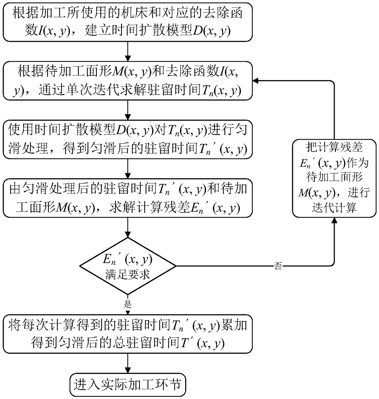
Since the surface error is introduced by the processing equipment during the machining process, and the correction of medium and high frequency surface error is the technical difficulty of current CNC machining, it is difficult to correct it through secondary processing

Method used


Image

  • Smoothing method for residence time in optical-element processing process
  • Smoothing method for residence time in optical-element processing process
  • Smoothing method for residence time in optical-element processing process

Examples


Embodiment

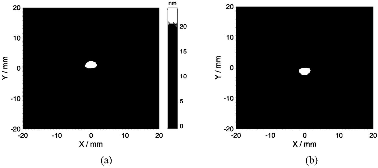
[0053] In this embodiment, the magnetorheological numerical control polishing machine is used as the processing equipment, and the circular flat mirror with a diameter of 100 mm is used as the component to be processed, and combined with Figure 2 to Figure 7 , to illustrate the specific embodiments of the present invention. In the following description, the method for smoothing the residence time during the processing of the optical element according to the present invention is referred to as the smoothing method for short. Under normal circumstances, the removal function of the magnetorheological polishing machine is non-circularly symmetrical, figure 2 (a) is the removal function distribution I(x, y) when the magneto-rheological polishing head stays at the coordinate point x=0, y=0 for 3 seconds. This embodiment takes figure 2 The shape distribution of the removal function distribution shown in (a) about x=0, y=0 coordinate point rotated 180 degrees is used as the time ...


PUM


Abstract

The invention discloses a smoothing method for residence time in the optical-element processing process. In the method, a time diffusion model is introduced, residence time distribution obtained afterconventional calculation is diffused, and therefore it is achieved that the residence time is smoothed. Compared with original residence time, in the residence time after smoothing treatment, time difference values on adjacent diffusion points are relatively small, smooth transition between the adjacent diffusion points is achieved accordingly, and the influence when a polishing tool is frequently accelerated and decelerated in the processing process on the tool stability is thus reduced. By means of the smoothing method for the residence time in the optical-element processing process, the convergence effect of calculation can be improved through time diffusion treatment, the jumping degree of the residence time between the adjacent diffusion points can also be reduced by smoothing the residence time, the stability of numerical control machining can be improved, and the medium frequency error and the high frequency error which are introduced in an element are thus reduced since the polishing tool frequently shakes.

Description

technical field [0001] The invention belongs to the processing field of optical elements, and in particular relates to a smoothing method for residence time in the processing process of optical elements. Background technique [0002] With the rapid development of optical technology and the continuous expansion of its application scope, people have put forward higher and higher requirements for the technical indicators such as surface accuracy and surface roughness of optical components. Aspheric surfaces, large relative apertures, and nanometer precision have become The development trend of modern optical components. In order to effectively improve the surface processing quality of optical components and meet the needs of modern high-precision processing technology, technicians began to use high-precision CNC machining machines for processing optical components. In the process of CNC machining, the polishing tool forms a certain relative movement speed and pressure on the s...

Claims


Application Information

Patent Timeline
Patent Type & Authority Applications(China)
IPC IPC(8): B24B1/00B24B13/00
CPCB24B1/00B24B13/00B24B49/02G06F17/153
Inventor 胡小川钟显云赖朝辉杨金山
Owner INST OF OPTICS & ELECTRONICS - CHINESE ACAD OF SCI
Why Eureka
Try Eureka