System and method for accumulating nitrite nitrogen in partial nitrification process

A short-range nitrification and nitrous nitrogen technology, applied in the field of ammonia nitrogen-containing sewage treatment, can solve the problems of poor operation stability and inconvenient system operation, and achieve the effects of small footprint, short process flow and high efficiency

Active Publication Date: 2019-01-18
HEBEI UNIVERSITY
View PDF2 Cites 0 Cited by
  • Summary
  • Abstract
  • Description
  • Claims
  • Application Information

AI Technical Summary

Problems solved by technology

[0005] One of the purposes of the present invention is to provide a system for accumulating nitrous nitrogen in the short-range nitrification process, so as to solve the problems of inconvenient operation and poor operation stability of the existing system

Method used


Image

  • System and method for accumulating nitrite nitrogen in partial nitrification process
  • System and method for accumulating nitrite nitrogen in partial nitrification process
  • System and method for accumulating nitrite nitrogen in partial nitrification process

Examples


Embodiment 1

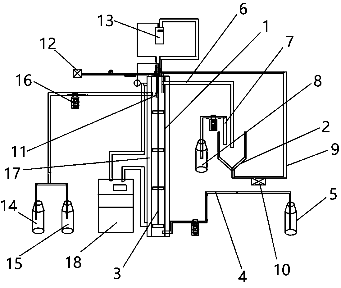
[0036] like figure 1As shown, the system structure of the present invention includes a stirred upflow reaction 1, a vertical flow sedimentation tank 2, a water quality monitoring device, an aeration device and an acid-base adjustment device. Stirred upflow reactor 1 is a cylindrical reactor with an aspect ratio of 10-15, and a stirring device 3 is provided in the cylindrical reactor, and the stirring device 3 includes a stirring rod arranged along the axis of the stirred upflow reactor 1. Stirring blades distributed on the stirring rod and a speed controller connected with the stirring rod. During operation, the stirring device can be controlled at an appropriate stirring speed by the speed controller as required.

[0037] The bottom of the stirred upflow reactor 1 is connected to the water inlet tank 5 through the water inlet pipe 4, and the top of the stirred upflow reactor 1 is connected to the vertical flow sedimentation tank 2 through the reactor outlet pipe 6, and the ve...

Embodiment 2

[0042] The method for accumulating nitrous nitrogen in the short-range nitrification process of the present invention comprises the following steps:

[0043] a. Set up the above-mentioned system for accumulating nitrous nitrogen, wherein the height of the stirred upflow reactor is 115 cm, and the inner diameter is 9.5 cm.

[0044] b. Add digested sludge from the aeration tank of Baoding Sewage Treatment Plant to the stirred upflow reactor. After adding, the MLSS is 4189 mg / L, and the surface aeration head, pH probe, dissolved oxygen probe and oxidation The reduction potential probe is submerged 17cm below the liquid surface.

[0045] c. Acclimatization stage: the DO at the dissolved oxygen probe is controlled to be 0.6~0.7mg / L, the pH is 7.5~8.5, the ORP is 10~200mV, the temperature is 25~35°C, and the concentration of ammonia nitrogen is set to 150mg / L and ammonia nitrogen concentration of 50mg / L wastewater are alternately fed into the water for domestication until the ammon...


PUM


Abstract

The invention provides a system for accumulating nitrite nitrogen in a partial nitrification process. The system comprises a stirring type upflow reactor, a settling tank, a water quality monitoring device, an aeration device and an acid-alkali adjusting device, wherein the stirring type upflow reactor is a cylindrical reactor with a high-diameter ratio of 10 to 15, and a stirring device is arranged in the cylindrical reactor; the aeration device comprises a surface-layer aeration head and an air pump, the surface-layer aeration head is arranged at the top of the stirring type upflow reactor,and the air pump is connected with the surface-layer aeration head through an air pipe; and the water quality monitoring device comprises a pH probe, a dissolved oxygen probe, an oxidation-reduction potential probe and a digital water-quality analyzer, and the digital water-quality analyzer is electrically connected with each probe. The invention further provides a method for accumulating nitritenitrogen by virtue of the system. The system is simple in structure, low in input cost, simple and convenient to operate, high in process stability and suitable for being popularized and applied.

Description

technical field [0001] The invention relates to the technical field of ammonia nitrogen-containing sewage treatment, in particular to a system and method for accumulating nitrite nitrogen in a short-range nitrification process. Background technique [0002] Most of my country's urban domestic sewage has low C / N, so the biological nitrification-denitrification process needs to add additional organic carbon sources, resulting in high operating costs. The anaerobic ammonium oxidation process can directly generate nitrogen gas from ammonia nitrogen and a certain proportion of nitrous nitrogen, which has the advantages of no need to add additional organic carbon sources, no need for aeration, no secondary pollution, and low operation and management costs. [0003] At present, the main direction of anaerobic ammonium oxidation research is domestic sewage, landfill leachate, industrial wastewater, sludge supernatant, pharmaceutical wastewater treatment, etc., but there is almost no...

Claims


Application Information

Patent Timeline
Patent Type & Authority Applications(China)
IPC IPC(8): C02F3/34C02F3/30C02F101/16
CPCC02F3/307C02F3/34C02F2203/004C02F2101/16
Inventor 路达李明秦哲栾永清高志琦郭子涵李馥佳史慧群
Owner HEBEI UNIVERSITY
Why Eureka
Try Eureka