Flow guiding type rotor internal combustion engine between rotor and stator

A rotor internal combustion engine and stator technology, applied in the direction of internal combustion piston engines, combustion engines, mechanical equipment, etc., can solve the problems of inability to realize the transformation of mechanical efficiency, the inability to eliminate power loss, and the low transformation of mechanical efficiency, so as to improve the efficiency of mechanical transformation and dynamic Balanced easy-to-master, light-weight effects

Inactive Publication Date: 2019-01-18
王亚东
View PDF5 Cites 1 Cited by
  • Summary
  • Abstract
  • Description
  • Claims
  • Application Information

AI Technical Summary

Problems solved by technology

[0003] At present, as far as the reciprocating internal combustion engine with cycle combustion is concerned, the conversion of mechanical efficiency is not high, and the reasons why the conversion efficiency cannot be continuously improved mainly include the following points: 1. Due to the mechanical structure of the reciprocating piston internal combustion engine, theoretically speaking, when When the combustible gas deflagrates, the torque of the crankshaft, connecting rod and power output shaft is on the same plane, that is to say, the pressure is perpendicular to the power output shaft, and the torque cannot be generated, so work cannot be realized. Only the piston descends the crank and the connecting rod The moment is only generated when the included angle is not 180°. When the arc drawn by the crankshaft and the connecting rod is close to the tangent, the moment is the largest. However, the pressure of the expanding gas is also constantly attenuating. When the torque is the largest, the pressure intensity of the gas expansion is also attenuation, so effective mechanical efficiency transitions cannot be achieved
2. Due to the inertia generated by the high-frequency reciprocating motion of the piston and connecting rod to offset part of the useful work, the output efficiency is reduced
3. Due to the complicated structure and huge movement accessories, some useful work is offset
At present, there is no effective means to optimize the efficiency loss in this area, and it is impossible to eliminate the power loss in this area

Method used


Image

  • Flow guiding type rotor internal combustion engine between rotor and stator
  • Flow guiding type rotor internal combustion engine between rotor and stator
  • Flow guiding type rotor internal combustion engine between rotor and stator

Examples


Embodiment Construction

[0033] In order to make the purpose, technical solutions and advantages of the embodiments of the present invention clearer, the technical solutions in the embodiments of the present invention will be clearly and completely described below in conjunction with the drawings in the embodiments of the present invention. Obviously, the described embodiments It is a part of embodiments of the present invention, but not all embodiments. Based on the embodiments of the present invention, all other embodiments obtained by persons of ordinary skill in the art without making creative efforts belong to the protection scope of the present invention.

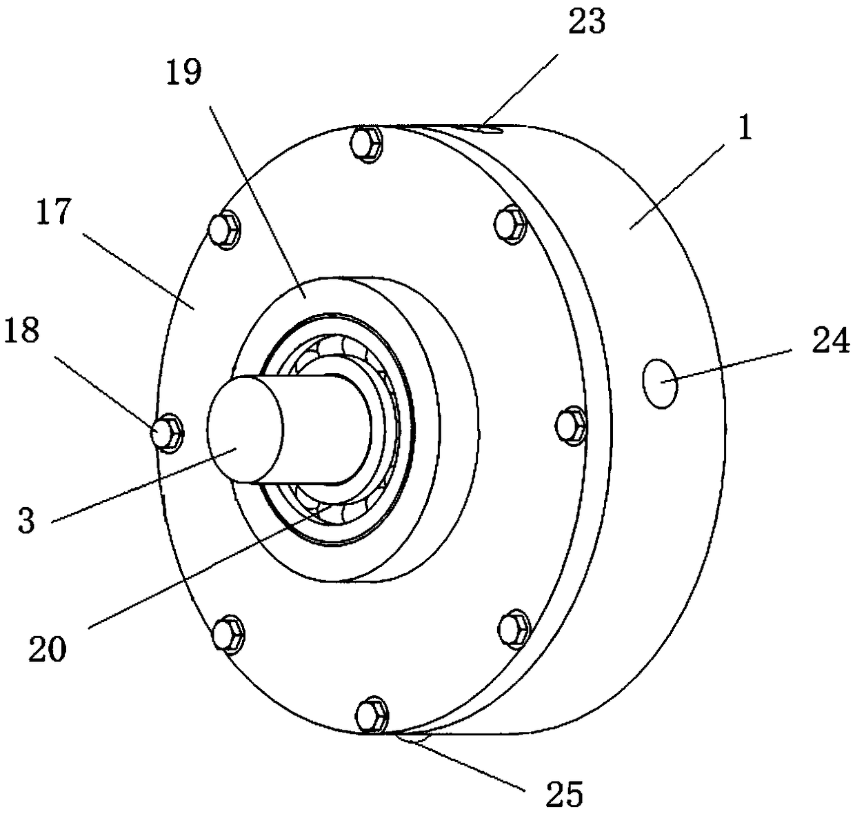
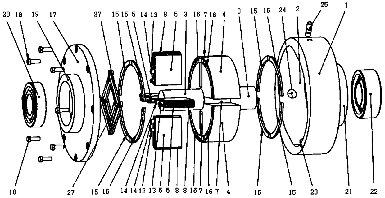
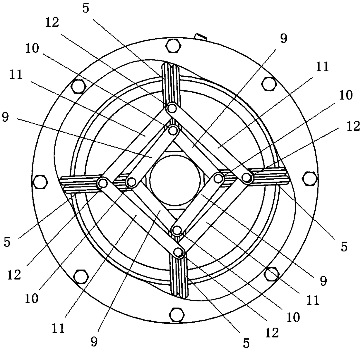
[0034] Such as Figure 1-5 As shown, the embodiment of the present invention provides a rotor-stator guided rotor internal combustion engine, including a rotor assembly and a stator assembly.

[0035] The stator assembly at least includes a stator body 1, the stator body 1 is provided with a stator cavity 2, and the inner wall of the stator ...


PUM


Abstract

The invention relates to the technical field of internal combustion engines, in particular to a flow guiding type rotor internal combustion engine between a rotor and a stator. The flow guiding type rotor internal combustion engine between the rotor and the stator comprises a rotor assembly and a stator assembly. The stator assembly comprises a stator body, the stator body is provided with a stator cavity, the inner wall of the stator cavity is formed by connecting four sections of arc hook faces in a smooth transition mode. The rotor assembly comprises a rotor shaft, a rotor body and four sets of servo airtight sliding plates, each set of servo airtight sliding plates are in closed sliding contact with the inner wall of the stator cavity, and the stator cavity is divided into four independent airtight cavities. According to the flow guiding type rotor internal combustion engine between the rotor and the stator, tangent line torque generated during gas expansion acting can be convertedinto one-way driving torque for circular motion, so that the power loss is effectively lowered, and the mechanical conversion efficiency of the rotor internal combustion engine is improved.

Description

technical field [0001] The invention relates to the technical field of internal combustion engines, in particular to a flow guide type rotor internal combustion engine between a rotor and a stator. Background technique [0002] Internal combustion engines using the Otto cycle (or Diesel cycle), whether reciprocating piston or Wankel triangular rotor internal combustion engines, or even gas turbines, are energy pulses that compress combustible gases and ignite (or compress ignite) the compressed combustible gas , the expansion gas generated, and then generate pressure to push the piston or other transmission components, and generate mechanical energy to achieve work. In other words, it is a device that converts chemical energy into mechanical energy. For internal combustion engines of the cycle combustion category, the working process follows the actions of intake, compression, work, and exhaust. [0003] At present, as far as the reciprocating internal combustion engine wit...

Claims


Application Information

Patent Timeline
IPC IPC(8): F02B53/04F02B53/02F02B55/02
CPCF02B53/02F02B53/04F02B55/02Y02T10/12
Inventor 王亚东
Owner 王亚东
Why Eureka
Try Eureka