Solid-liquid separation processor

A technology of solid-liquid separation and processor, applied in the direction of filtration separation, sludge treatment, separation methods, etc., can solve the problem of shortening the processing time and processing cost of the filter screen, and achieve the effect of large gap on the back

Pending Publication Date: 2019-01-25
禹州华德环保科技有限公司
View PDF3 Cites 10 Cited by
  • Summary
  • Abstract
  • Description
  • Claims
  • Application Information

AI Technical Summary

Problems solved by technology

[0003] The purpose of the present invention is to overcome the deficiencies of the prior art, and provide a reasonable structure design, simple and convenient operation, high separation and collection efficiency, not easy to clog the filter screen, uniform and thorough separation, shorten processing time, reduce processing cost and suitable for large Solid-liquid separation processor for large-scale processing

Method used


Image

  • Solid-liquid separation processor
  • Solid-liquid separation processor

Examples


Embodiment 1

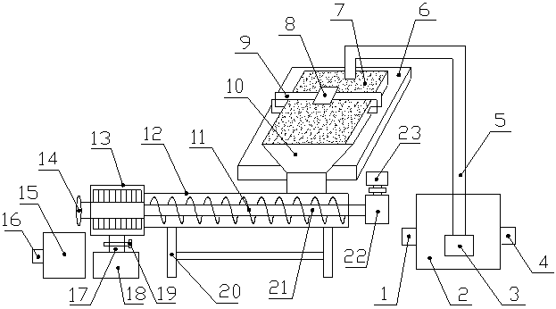
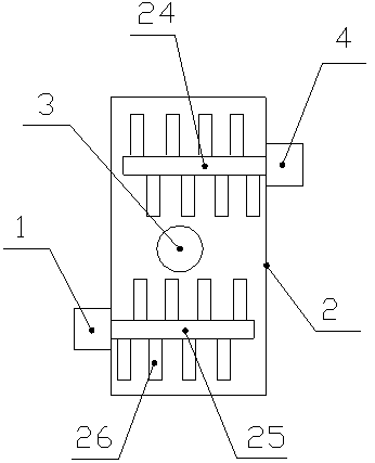
[0013] like Figure 1-2 Shown, a kind of solid-liquid separation processing machine, it comprises slag-liquid storage box 2 and extrusion screw conveyor 12, the left front part of described slag-liquid storage box 2 is connected with stirring motor A1, and described stirring motor The output shaft of A1 is connected with the stirring shaft A25, the stirring shaft A25 penetrates the left side wall of the slag liquid storage tank 2 and extends into the slag liquid storage tank 2, the right rear part of the slag liquid storage tank 2 A stirring motor B4 is connected, and the output shaft of the stirring motor B4 is connected with a stirring shaft B24, and the stirring shaft B24 penetrates the right side wall of the slag liquid storage tank 2 and extends into the slag liquid storage tank 2. Stirring blades 26 are fixedly installed on the stirring shaft A1 and the stirring shaft B24, a submersible cutting pump 3 is arranged in the middle of the slag liquid storage tank 2, and a dis...

Embodiment 2

[0016] like Figure 1-2 Shown, a kind of solid-liquid separation processing machine, it comprises slag-liquid storage box 2 and extrusion screw conveyor 12, the left front part of described slag-liquid storage box 2 is connected with stirring motor A1, and described stirring motor The output shaft of A1 is connected with the stirring shaft A25, the stirring shaft A25 penetrates the left side wall of the slag liquid storage tank 2 and extends into the slag liquid storage tank 2, the right rear part of the slag liquid storage tank 2 A stirring motor B4 is connected, and the output shaft of the stirring motor B4 is connected with a stirring shaft B24, and the stirring shaft B24 penetrates the right side wall of the slag liquid storage tank 2 and extends into the slag liquid storage tank 2. Stirring blades 26 are fixedly installed on the stirring shaft A1 and the stirring shaft B24, a submersible cutting pump 3 is arranged in the middle of the slag liquid storage tank 2, and a dis...


PUM


Abstract

The invention discloses a solid-liquid separation processor. The solid-liquid separation processor comprises a slag liquid storage box and an extrusion screw conveyor, a stirring motor A is connectedto the front part of the left side of the slag liquid storage box, a stirring shaft A is connected with the output shaft of the stirring motor A, a stirring motor B is connected with the rear part ofthe right side of the slag liquid storage box, and a stirring shaft B is connected with the output shaft of the stirring motor B; stirring blades are installed on the stirring shaft A and the stirringshaft B, a diving cutting pump is arranged in the middle of the slag liquid storage box, a discharging pipe is connected with the output end of the diving cutting pump, a filter sieve net is arrangedbelow the other end of the discharging pipe, and a feeding hopper is connected with the front end of the filter sieve net; and an extrusion drying box is connected with the left end of the extrusionscrew conveyor, the left side of the extrusion drying box is provided with a discharging port, and the lower end of the extrusion drying box is provided with a liquid outlet. The solid-liquid separation processor has the advantages that the operation is easy and convenient, the separation and collecting efficiency is high, the filter sieve net is not prone to being blocked, separation is even andthorough, the processing time is shortened, the processing cost is lowered, and the processor is suitable for large-scale processing.

Description

technical field [0001] The invention relates to the technical field of solid-liquid separation equipment, in particular to a solid-liquid separation processor. Background technique [0002] The development of modern livestock and poultry breeding industry and the rise of factory intensive farming have enriched people's material needs, but also brought about the flooding of livestock and poultry sewage, causing pollution to water sources, air and the environment. Solid-liquid separator treatment The machine is an environmental protection equipment for livestock and poultry manure dewatering. It can separate the raw manure and sewage of poultry manure into liquid organic fertilizer and solid organic fertilizer. The liquid organic fertilizer can be used for crop utilization and absorption, and the solid organic fertilizer can be transported. It can also improve the soil structure when used in fertilizer-deficient areas. At the same time, it can be fermented to make organic comp...

Claims


Application Information

Patent Timeline
Patent Type & Authority Applications(China)
IPC IPC(8): B01D33/03B01D33/64B01D33/72B01D33/76B01D33/80B01F7/04B01F15/02C02F11/121
CPCB01D33/0353B01D33/648B01D33/72B01D33/76B01D33/80C02F11/121B01F27/701B01F35/7544
Inventor 张中义马跃东
Owner 禹州华德环保科技有限公司
Why Eureka
Try Eureka