Supercharge Your Innovation With Domain-Expert AI Agents!

A kind of rapid plasma coating method and device

A technology of plasma and coating device, applied in the field of plasma coating method and device, can solve the problem of slow coating speed, etc., and achieve the effect of rapid film formation and accelerated melting

Active Publication Date: 2021-12-17
PINGGAO GRP +2
View PDF11 Cites 0 Cited by
  • Summary
  • Abstract
  • Description
  • Claims
  • Application Information

AI Technical Summary

Problems solved by technology

[0006] The purpose of the present invention is to provide a fast plasma coating method and device, which is used to solve the problem of slow coating speed caused by using the anode as the coating source electrode

Method used


Image

  • A kind of rapid plasma coating method and device
  • A kind of rapid plasma coating method and device

Examples


Embodiment Construction

[0023] The specific embodiments of the present invention will be further described below in conjunction with the accompanying drawings.

[0024] Such as figure 1 The shown rapid plasma coating device includes a vacuum chamber, and a cathode and an anode assembled in the vacuum chamber. Among them, the vacuum chamber includes an insulating shell 1, a cathode side end cover 2 and an anode side end cover 3 to form a closed space, and the inside of the closed space is a vacuum degree of 10 -3 Vacuum state of Pa and above. The cathode conductive rod 4 passes through and is fixed on the cathode side end cover 2. The first port of the cathode conductive rod 4 is outside the confined space and extends along the outside of the cathode side end cover 2 for connecting the cathode of the DC power supply; the cathode conductive rod The second port of 4 is located in the closed space and is connected to the disk-shaped cathode 6. The anode conductive rod 5 passes through and is fixed on ...


PUM


Abstract

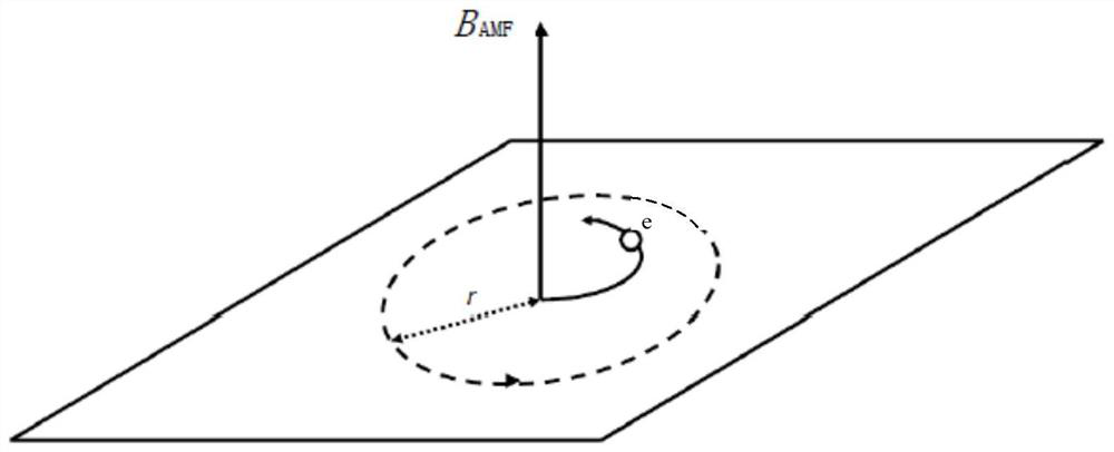
The invention relates to a fast plasma coating method and device. By setting a conductive coil outside the vacuum chamber, the longitudinal magnetic field generated by the conductive coil is used to concentrate the energy of the vacuum arc on the anode, so that the material of the anode evaporates, and the coating object is guaranteed fast coating. The invention not only avoids the impact of large particles produced by the cathode on the film quality, but also can control the arc energy to be concentratedly injected into the anode through the effect of the longitudinal magnetic field generated by the conductive coil, accelerate the melting of the anode contact, and enable the coating object to be quickly formed into a film.

Description

technical field [0001] The invention belongs to the technical field of vacuum electroplating, and in particular relates to a fast plasma coating method and device. Background technique [0002] Vacuum arc coating (VAC) technology, as an important branch of physical vapor deposition technology, has been developed rapidly and widely used in recent years. Since its appearance in the 1960s, VAC has shown strong vitality and gained rapid adoption due to its high deposition rate, strong film adhesion, easy preparation of difficult-to-obtain alloys, simple process, and no pollution. develop. VAC technology uses cathode arc discharge, with the cathode as the target source electrode and the anode as the auxiliary electrode. This structure can bring many advantages, such as the "three highs" characteristics of high ionization rate, high energy, and high production efficiency, but At the same time, it also brought some problems. Among them, the most notable is the problem of macrosc...

Claims


Application Information

Patent Timeline
Patent Type & Authority Patents(China)
IPC IPC(8): C23C14/32
CPCC23C14/325
Inventor 卢彦辉李世民韩桂全李昊旻韩国辉张超军王建华毕迎华李旭旭刘志远刘庆丁健刚
Owner PINGGAO GRP
Features
  • R&D
  • Intellectual Property
  • Life Sciences
  • Materials
  • Tech Scout
  • Unparalleled Data Quality
  • Higher Quality Content
  • 60% Fewer Hallucinations
Learn More