
Imaging system and imaging method

An imaging system and imaging method technology, applied in the field of imaging systems, can solve the problems of sudden increase in data transmission bandwidth, unfavorable noise suppression, and limited exposure time, etc., and achieve the requirements of reducing system transmission bandwidth, good image noise suppression, and cost reduction Effect

Inactive Publication Date: 2019-01-29
OMNIVISION TECH (SHANGHAI) CO LTD
View PDF6 Cites 7 Cited by
  • Summary
  • Abstract
  • Description
  • Claims
  • Application Information

AI Technical Summary

Problems solved by technology

However, this method needs to synchronize the exposure time of the image sensor with the switching time of the light source (including infrared light source and visible light source), requires an accurate synchronization device, and needs to take multiple frames of images in order to obtain a composite frame. The continuity of the image needs to be obtained at a very high frame rate, which will lead to a sudden increase in the data transmission bandwidth, and the exposure time is limited, which is not conducive to noise suppression. The system is complex, the requirements are high, and the cost is bound to be high.

Method used


Image

  • Imaging system and imaging method
  • Imaging system and imaging method
  • Imaging system and imaging method

Examples


Embodiment Construction

[0041] The specific implementation manner of the present invention will be described in more detail below with reference to schematic diagrams. Advantages and features of the present invention will be apparent from the following description and claims. It should be noted that all the drawings are in a very simplified form and use imprecise scales, and are only used to facilitate and clearly assist the purpose of illustrating the embodiments of the present invention.

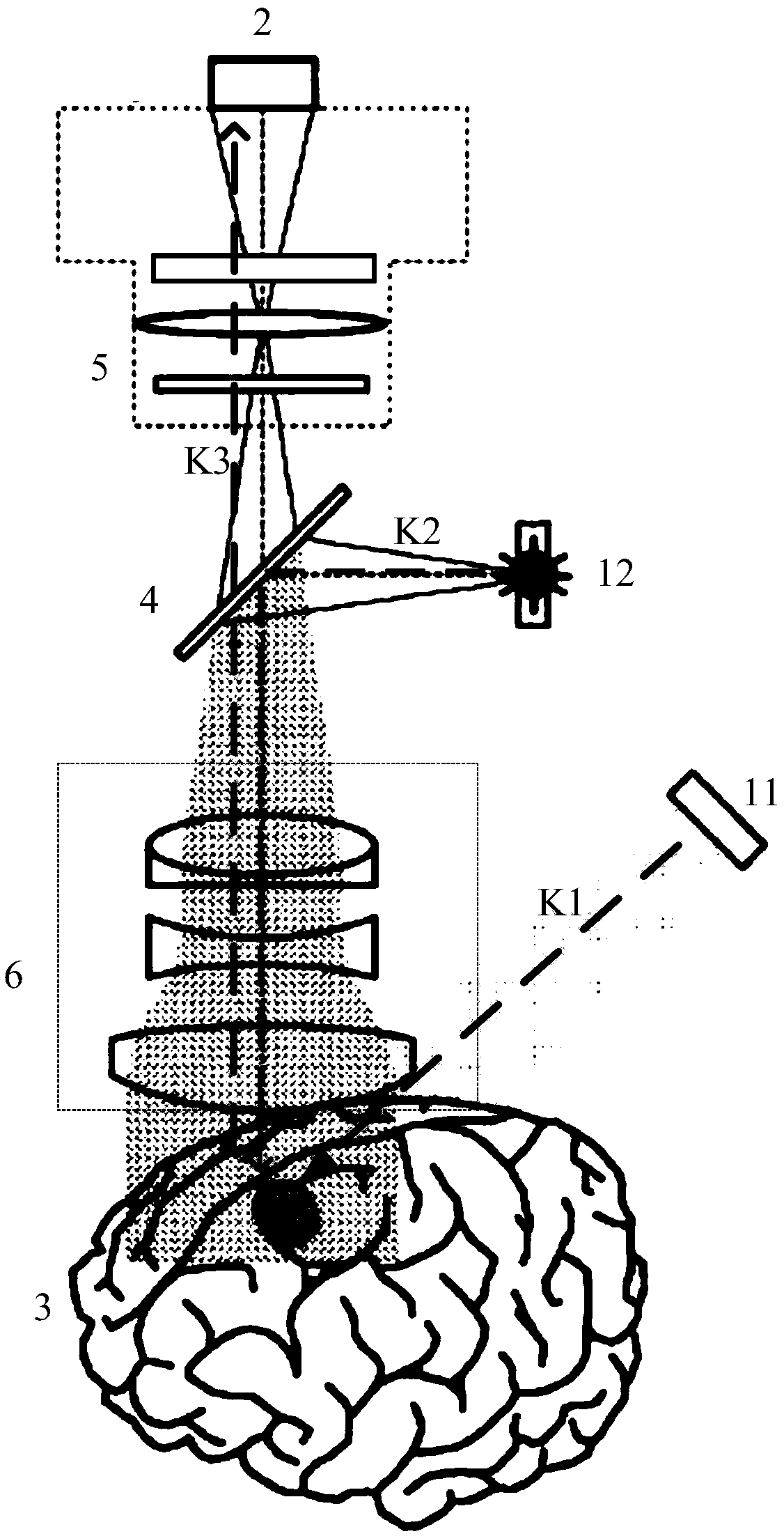
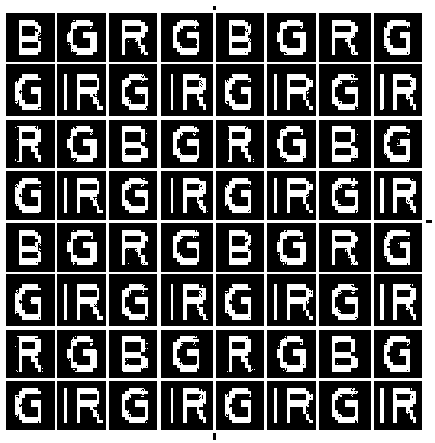
[0042] see figure 1 , which is a schematic structural diagram of the imaging system provided in this embodiment, such as figure 1 As shown, the imaging system includes a light source module, a first optical path K1, a second optical path K2, a third optical path K3 and an RGBIR image sensing module 2, and the light source includes a visible light source 11 and an infrared light source 12; the visible light source The white light emitted by 11 is irradiated onto a sample 3 carrying a fluorophore along the first ...


PUM


Abstract

The invention provides an imaging system and an imaging method. White light and infrared light are adopted to irradiate a sample carrying fluorophores at the same time, the white light is reflected toform a first signal light, the fluorophores are excited to form a second signal light, an RGBIR image sensing module obtains a first RGBIR image signal of the sample according to the first signal light and the second signal light, and only one shoot is needed to obtain the first RGBIR image signal. The imaging system and the imaging method greatly reduce the amount of data needed to acquire the same data, reduce the requirement on a transmission bandwidth of the system, effectively improve the exposure adjustment time, can obtain better image noise suppression, have lower requirement on the exposure frequency of the RGBIR image sensing module, can use a rolling shutter image sensor with low price, and reduce the costs.

Description

technical field [0001] The present invention relates to the technical field of imaging systems, in particular to an imaging system and an imaging method. Background technique [0002] In recent years, methods that use infrared (IR) dyes to label tissues such as tumors and blood vessels to form fluorophores during surgical removal of tumors in a clinical setting have attracted attention. Infrared dyes are considered to be excellent labeling dyes for labeling tissues, and the use of these dyes to label tissue and use in, for example, clinical operating room environments requires the use of IR-sensitive imaging systems (such as CCD image sensors) in alternating use of infrared light illumination and In the case of visible light illumination, the infrared image signal and the visible light image signal are collected separately, and the infrared image signal is superimposed on the visible light image signal to provide a contrast for the surgeon during operation, so that the surge...

Claims


Application Information

Patent Timeline
Patent Type & Authority Applications(China)
IPC IPC(8): A61B5/00G06T5/50G06T5/00
CPCA61B5/0059A61B5/0071G06T5/50A61B5/72G06T2207/30096G06T2207/10048G06T5/77G06T5/70
Inventor 杨松岸汤晓莉
Owner OMNIVISION TECH (SHANGHAI) CO LTD
Learn More